MOBILE PHONE REPAIRING GUIDE

laal

Member
Apr 18, 2008
185
9
0
Fuse

In electronics and electrical engineering a fuse (from the Latin "fusus" meaning to melt) is a type of sacrificial overcurrent protection device. Its essential component is a metal wire or strip that melts when too much current flows, which interrupts the circuit in which it is connected. Short circuit, overload or device failure is often the reason for excessive current.

Smt%20fuse.jpg
A fuse interrupts excessive current (blows) so that further damage by overheating or fire is prevented. Wiring regulations often define a maximum fuse current rating for particular circuits. Overcurrent protection devices are essential in electrical systems to limit threats to human life and property damage. Fuses are selected to allow passage of normal current and of excessive current only for short periods.

A fuse was patented by Thomas Edison in 1890 [1] as part of his successful electric distribution system.
 

laal

Member
Apr 18, 2008
185
9
0
Coils & Inductors

An inductor or a reactor is a passive electrical component that can store energy in a magnetic field created by the electric current passing through it. An inductor's ability to store magnetic energy is measured by its inductance, in units of henries. Typically an inductor is a conducting wire shaped as a coil, the loops helping to create a strong magnetic field inside the coil due to Faraday's Law of Induction. Inductors are one of the basic electronic components used in electronics where current and voltage change with time, due to the ability of inductors to delay and reshape alternating currents.

smt%20coils.jpg

Inductance (L) (measured in henries) is an effect resulting from the magnetic field that forms around a current-carrying conductor which tends to resist changes in the current. Electric current through the conductor creates a magnetic flux proportional to the current, and a change in this current creates a corresponding change in magnetic flux which, in turn, by Faraday's Law generates an electromotive force (EMF) that opposes this change in current. Inductance is a measure of the amount of EMF generated per unit change in current. For example, an inductor with an inductance of 1 henry produces an EMF of 1 volt when the current through the inductor changes at the rate of 1 ampere per second. The number of loops, the size of each loop, and the material it is wrapped around all affect the inductance. For example, the magnetic flux linking these turns can be increased by coiling the conductor around a material with a high permeability such as iron. This can increase the inductance by 2000 times, although less so at high frequencies.

Smt%20Transformer.jpg

Inductors are used extensively in analog circuits and signal processing. Inductors in conjunction with capacitors and other components form tuned circuits which can emphasize or filter out specific signal frequencies. Applications range from the use of large inductors in power supplies, which in conjunction with filter capacitors remove residual hums known as the Mains hum or other fluctuations from the direct current output, to the small inductance of the ferrite bead or torus installed around a cable to prevent radio frequency interference from being transmitted down the wire. Smaller inductor/capacitor combinations provide tuned circuits used in radio reception and broadcasting, for instance.
 

DJ Hafeez

Well-known member
  • Oct 21, 2006
    1,493
    25
    48
    Everywhere my friends are
    My Nokia 5800 Xpress Music phone has some problem.
    The camera isn't working (when u click the cam button,a black screen appears and then again goes back to menu)
    There is a charging problem also,but the problem is not with the pin (i checked by changing it )
    The accelerometer is also not working.
    Can u please tell me how to repair it?
    HELP
     

    pavithra_uk

    Well-known member
  • Oct 6, 2009
    53,379
    22,029
    113
    Gotland
    My Nokia 5800 Xpress Music phone has some problem.
    The camera isn't working (when u click the cam button,a black screen appears and then again goes back to menu)
    There is a charging problem also,but the problem is not with the pin (i checked by changing it )
    The accelerometer is also not working.
    Can u please tell me how to repair it?
    HELP

    :oo:
    may be software fault

    hard reset device.
    if not corrected, full flash

    :( even this can cause hardware failures
     

    laal

    Member
    Apr 18, 2008
    185
    9
    0
    Nokia 5800 XpressMusic Not Charging Repair Guide

    This is a step by step procedure on how to fix Nokia 5800 xpressmusic not charging problem issues.
    1. Use and try different charger, a good and working one, may help undentify if the charger is working
    perfectly or not, check the charger voltage if there is a voltage flow across to it.
    2. Replace a good and working Battery, a weak battery voltage may also occurs not charging issues, you
    can also check and test the desired battery voltage.
    3. if the problem still exist, Disassemble the handset.
    4. Check the charging connector pin. make sure if it is clean, free from molds or corrosion and in properly
    allignment to the PCB contact pads. replace if found damaged.
    5. Trace the charging voltage path lines and components using the picture guides below.
    A. Check the Charger Voltage Line Paths
    . B. Check all Charging Components and replace if found busted or faulty.


    NOKIA 5800 Xpressmusic PCB layout of charging components​
     

    laal

    Member
    Apr 18, 2008
    185
    9
    0
    5800 camera

    if not 1.. check camera & its connector ..
    2.. is it ok then change camera IC
     

    laal

    Member
    Apr 18, 2008
    185
    9
    0
    coil

    An inductor or a reactor is a passive electrical component that can store energy in a magnetic field created by the electric current passing through it. An inductor's ability to store magnetic energy is measured by its inductance, in units of henries. Typically an inductor is a conducting wire shaped as a coil, the loops helping to create a strong magnetic field inside the coil due to Faraday's Law of Induction. Inductors are one of the basic electronic components used in electronics where current and voltage change with time, due to the ability of inductors to delay and reshape alternating currents.

    smt%20coils.jpg

    Inductance (L) (measured in henries) is an effect resulting from the magnetic field that forms around a current-carrying conductor which tends to resist changes in the current. Electric current through the conductor creates a magnetic flux proportional to the current, and a change in this current creates a corresponding change in magnetic flux which, in turn, by Faraday's Law generates an electromotive force (EMF) that opposes this change in current. Inductance is a measure of the amount of EMF generated per unit change in current. For example, an inductor with an inductance of 1 henry produces an EMF of 1 volt when the current through the inductor changes at the rate of 1 ampere per second. The number of loops, the size of each loop, and the material it is wrapped around all affect the inductance. For example, the magnetic flux linking these turns can be increased by coiling the conductor around a material with a high permeability such as iron. This can increase the inductance by 2000 times, although less so at high frequencies.

    Smt%20Transformer.jpg

    Inductors are used extensively in analog circuits and signal processing. Inductors in conjunction with capacitors and other components form tuned circuits which can emphasize or filter out specific signal frequencies. Applications range from the use of large inductors in power supplies, which in conjunction with filter capacitors remove residual hums known as the Mains hum or other fluctuations from the direct current output, to the small inductance of the ferrite bead or torus installed around a cable to prevent radio frequency interference from being transmitted down the wire. Smaller inductor/capacitor combinations provide tuned circuits used in radio reception and broadcasting, for instance
     

    laal

    Member
    Apr 18, 2008
    185
    9
    0
    How To Solder SMD Components Manually by Hand

    Proper Soldering and De-soldering Methods and Techniques on Surface Mount Components

    Soldering is the process of using a metal alloy with a low melting temperature (solder) to Fuse the the electrical contacts of a component to the pads of a circuit board. Proper soldering maximizes the strength and conductivity of the connection. Poor soldering can result in weak connections, higher resistance that causes heat buildup at the connection, and possible failure of the component.

    The type of components and the pads to which they will be attached dictate the appropriate soldering method. The correct amount and duration of heat to be applied is a function of the heat transfer characteristics of the component, the circuit board, the solder pads, the solder and flux, and the environment, in which the soldering takes place. For this reason, effective soldering requires reasonably controlled. Some experimentation is usually required to determine the optimal conditions for each application.

    General Soldering Guides
    All soldering applications require the following considerations:
    * Preparation - Clean connections are essential to soldering. Clean connection maximize the ability of the solder to adhere uniformly to the joint surfaces ((welting).
    * Soldering Method - The component type and size and your specific application determine the soldering method.
    * Materials Selection - The component contacts, circuit board pads, solder,and flux materials must be compatible with soldering method.
    * Maximum Temperature - The soldering materials and method determine the temperature profile. All components must be able to withstand the maximum exposure temperature of the soldering operation for specified time and duration.

    Manual (Hand) Soldering Technique
    While the amount of solder, and the amount and duration of heat to be applied are application-specific, the following general hand-soldering guidelines will lead to consistent and reliable solder connections. A hot air gun is proffered for even heat application and control. The following techniques applies to hand soldering of surface mount components using solder wires and soldering iron.

    Preparation
    Before beginning to the soldering process, identify the solder composition
    and flux type. The solder type dictates the appropriate temperature of the soldering iron tips. Use small diameter wire solder for soldering small SMT components.
    Select an appropriate size tip before heating the soldering iron for a fine work result. Clean the tip of any oxidation or contamination. Place a sponge soaked in cold water, nearby for frequent tip cleaning between soldering operations.
    Clean the electronic component's contact/leads and the circuit board pads of any contamination or residue.


    Hot Air Gun and Soldering Iron Temperature Settings
    Hot air temperature temperature tends to be variable when working on any SMD components various Mobile Phones Products used different kinds of solders, check the manufacturer recomendations for specific solder types. The solder manufacturer may only provide the melting temperature range, so you may have to experiment to determine the appropriate temperature.
    The amount temperature on Hot Air gun commonly setting is between 250-350 degrees Celsius.
    While soldering iron is between 200 to 280 degree Celsius.


    This procedure covers the general guidelines for soldering surface mount chip components. The following surface mount chip components are covered by this procedure. While all of these components are different, the techniques for soldering are relatively similar
    Chip Resistors
    The component body of chip resistors is made out of alumna; an extremely hard, white colored material. The resistive material is normally located on the top. Chip resistors are usually mounted with the resistive element facing upwards to help dissipate heat.


    Ceramic Capacitors
    These components are constructed from several layers of ceramic with internal metallized layers. Because metal heats up much faster than ceramic, ceramic capacitors need to be heated slowly to avoid internal separations between the ceramic and the metal layers. Internal damage will not generally be visible, since any cracks will be inside the ceramic body of the component.
    NOTE

    Avoid rapid heating of ceramic chip capacitors during soldering operations.


    . Plastic Body
    Another style of chip component has a molded plastic body that protects the internal circuitry. There are a number of different types of components that share this type of exterior package. The termination styles for plastic chip component packages vary considerably.

    MELF

    MELF - Metal Electrode Face cylindrical components. These may be capacitors, resistors, and diodes. It can be hard to tell them apart - since there is no universal coloring or component designators printed on the component bodies.


    Replacing SMD Component on Printed Circuit Board
    De-soldering and Soldering Hand Method

    TOOLS & MATERIALS

    Cleaner

    Flux

    Microscope or
    Magnifying Glass lamp

    Solder

    Soldering Iron with Tips

    Rework Station Hot Air

    Wipes

    PROCEDURES TO REMOVE SMD COMPONENT

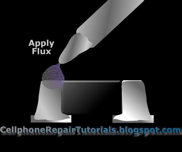
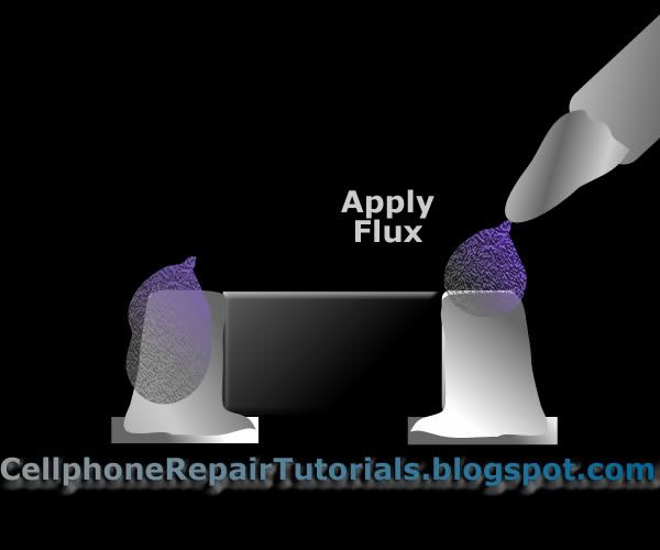
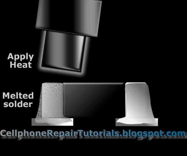
    Add liquid flux to both terminal pad.


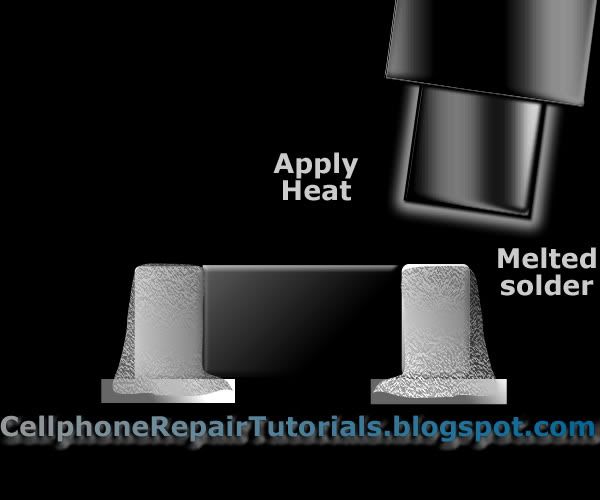
    Apply Desired Amount of heat on both sides of the leads.


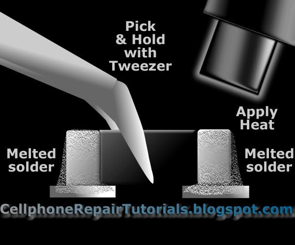
    Use a Tweezer to hold the component and observed until the solder joint is melted.

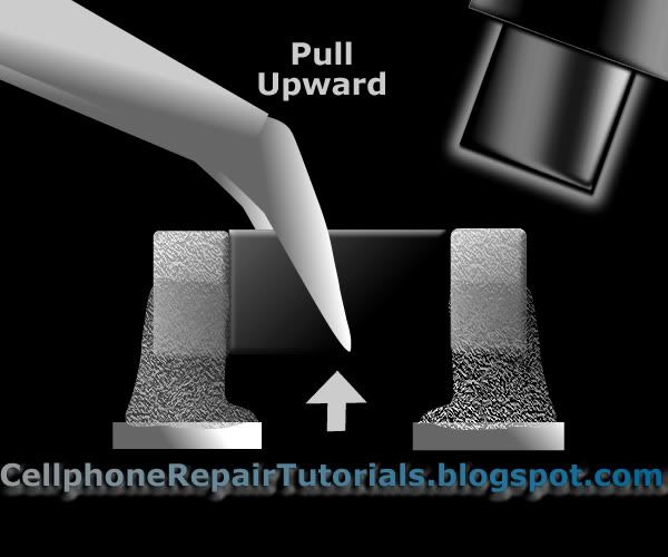
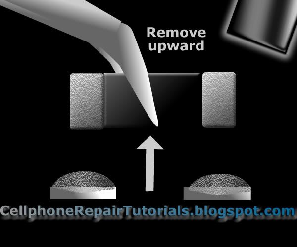
    Slowly pull in upward direction, when solders are already melted. do not pull upward forcibly when the solder is not melted yet. You might end up lifted the the terminal surface pads.


    PROCEDURE TO REPLACE SMD COMPONENT

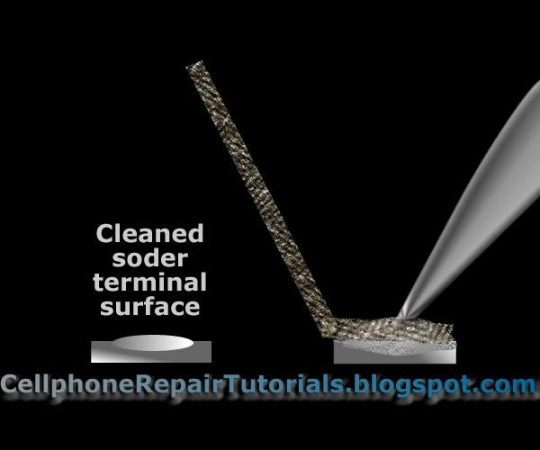
    Clean the surface terminal pads with cleaning kits.
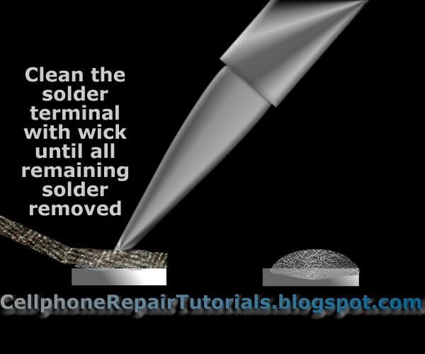
    Removed remaining old solders by using solder wick


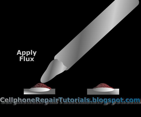
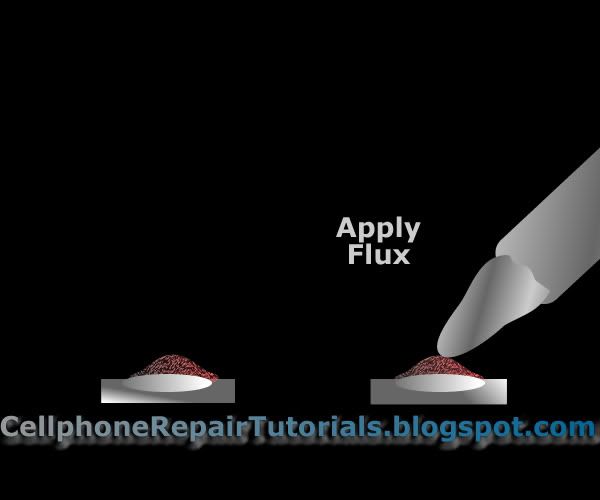
    When the pads is cleaned, Apply adequate amount of flux into the pads.


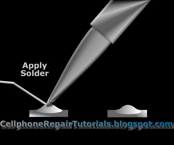
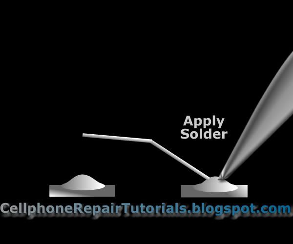
    Then apply both pads with fresh solder with desired heat controlled soldering iron.


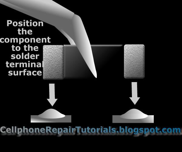
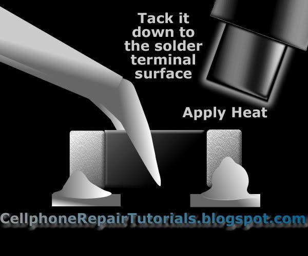
    Place the component in position and hold it steady with a tweezers so that the hot air won't push the component out of alignment.

    Tack it down and apply heat

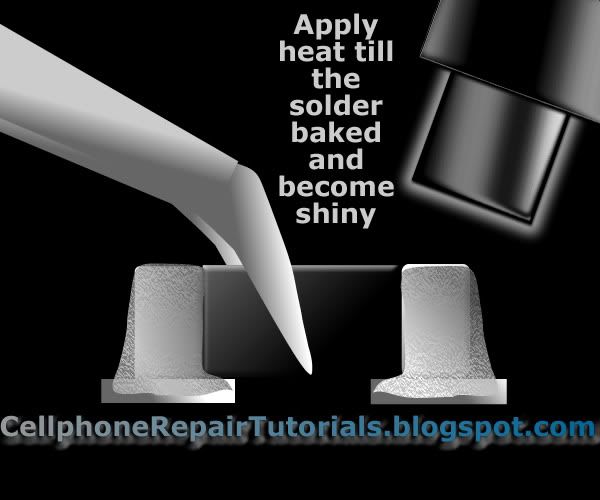
    Wait a moment for the solder to solidify both leads terminal.

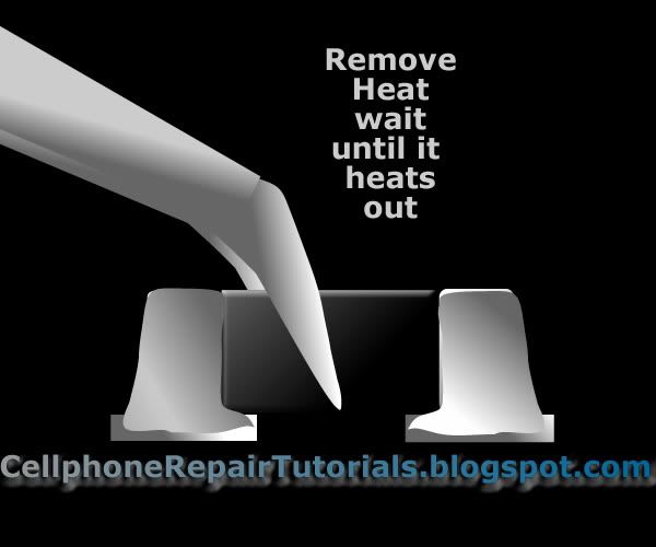
    Remove heat and hold the SMD components with tweezer until the heats out and cool.


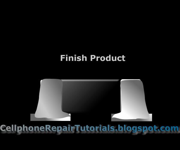
    Cleaned the surrounding areas with cleaning kit.


    You can practice by doing this with an old and non working cellphone PC Board. The more you do practice the more you will master it. Also observed and always become familiar of Hot air and soldering iron temperature settings. In my experience various type of cellphones solders have different melting point of the solder leads. There are too soft and there are also hard soldered leads to removed.
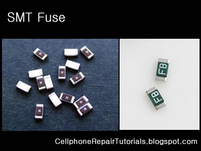
     

    laal

    Member
    Apr 18, 2008
    185
    9
    0
    Oscillators

    An electronic oscillator is an electronic circuit that produces a repetitive electronic signal, often a sine wave or a square wave.
    A low-frequency oscillator (LFO) is an electronic oscillator that generates an AC waveform at a frequency below ≈20 Hz. This term is typically used in the field of audio synthesizers, to distinguish it from an audio frequency oscillator.
    Oscillators designed to produce a high-power AC output from a DC supply are usually called inverters.
    The waveform generators which are used to generate pure sinusoidal waveforms of fixed amplitude and frequency are called oscillators.

    Crystal oscillator
    A crystal oscillator is an electronic circuit that uses the mechanical resonance of a vibrating crystal of piezoelectric material to create an electrical signal with a very precise frequency. This frequency is commonly used to keep track of time (as in quartz wristwatches), to provide a stable clock signal for digital integrated circuits, and to stabilize frequencies for radio transmitters and receivers. The most common type of piezoelectric resonator used is the quartz crystal, so oscillator circuits designed around them were called "crystal oscillators".

    Quartz crystals are manufactured for frequencies from a few tens of kilohertz to tens of megahertz. More than two billion (2×10⁹) crystals are manufactured annually. Most are small devices for consumer devices such as wristwatches, clocks, radios, computers, and cellphones. Quartz crystals are also found inside test and measurement equipment, such as counters, signal generators, and oscilloscopes.

    Smt%20clock.jpg

    Voltage-controlled oscillator


    A voltage-controlled oscillator or VCO is an electronic oscillator designed to be controlled in oscillation frequency by a voltage input.
    SMT%20VCTXO.png
    The frequency of oscillation is varied by the applied DC voltage, while modulating signals may also be fed into the VCO to cause frequency modulation (FM) or phase modulation (PM); a VCO with digital pulse output may similarly have its repetition rate (FSK, PSK) or pulse width modulated (PWM).