අයන්නේ සිට ඉලෙකට්‍රොනික්ස්.....

Little DJ

Well-known member
  • Nov 29, 2010
    1,014
    311
    83
    Panadura
    අයන්නේ සිට ඉලෙකට්‍රොනික්ස්.....


    Georg Simon Ohm


    Georg Simon Ohm was born in Erlangen, Bavaria, on March 16, 1787. His father was a master mechanic who determined that his son should obtain an education in science. Although Ohm became a teacher in a high school, he had aspirations to receive a university appointment. The only way that such an appointment could be realized would be if Ohm could produce important results through scientific research. Since the science of electricity was in its infancy, and because the electric cell had recently been invented by the Italian Conte Alessandro Volta, Ohm decided to study the behavior of current in resistive circuits. Because equipment was expensive and hard to come by, Ohm made much of his own, thanks, in large part, to his father’s training. Using this equipment, Ohm determined experimentally that the amount of current transmitted along a wire was directly proportional to its cross-sectional area and inversely proportional to its length. From these results, Ohm was able to define resistance and show that there was a simple relationship between voltage, resistance, and current. This result, now known as Ohm’s law, is probably the most fundamental relationship in circuit theory. However, when published in 1827, Ohm’s results were met with ridicule. As a result, not only did Ohm miss out on a university appointment, he was forced to resign from his high-school teaching position. While Ohm was living in poverty and shame, his work became known and appreciated outside Germany. In 1842, Ohm was appointed a member of the Royal Society. Finally, in 1849, he was appointed as a professor at the University of Munich, where he was at last recognized for his important contributions.

    Ohm's Law
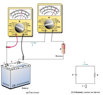


    Ohm determined experimentally that current in a resistive circuit is directly proportional to its applied voltage and inversely proportional to its resistance.

    I = V / R

    V
    is the voltage in volt
    R
    is the resistance in ohm
    I
    is the current in ampere

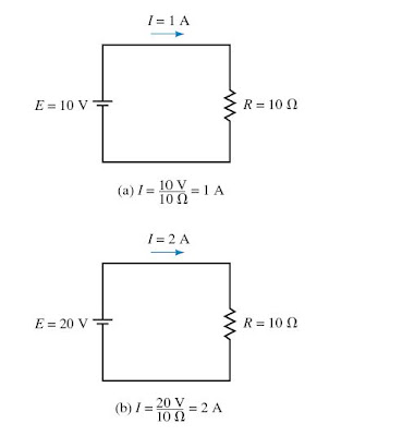
    Its determine that that larger the applied voltage, larger the current, while larger the resistance, smaller the current.


    Examples:


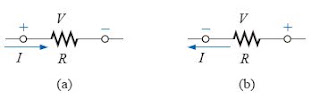
    For an isolated resistive element, the polarity of the voltage drop is as shown in following figure (a) for the indicated current direction. A reversal in current will reverse the polarity as in figure (b). In general, the flow of charge is from a high (+) to a low (-) potential. Polarities as established by current direction will become increasingly important in the circuit analysis.


    For More Details: Click Here


    Little DJ

    Well-known member
  • Nov 29, 2010
    1,014
    311
    83
    Panadura
    Kirchhoff Laws

    Gustav Robert Kirchhoff


    df.JPG


    Kirchhoff was a German physicist born on March 12, 1824, in Königsberg, Prussia. His first research was on the conduction of electricity, which led to his presentation of the laws of closed electric circuits in 1845. Kirchhoff’s current law and Kirchhoff’s voltage law apply to all electrical circuits and therefore are fundamentally important in understanding circuit operation. Kirchhoff was the first to verify that an electrical impulse travelled at the speed of light. Although these discoveries have immortalized Kirchhoff’s name in electrical science, he is better known for his work with R. W. Bunsen in which he made major contributions in the study of spectroscopy and advanced the research into black body radiation. Kirchhoff died in Berlin on October 17, 1887.


    Kirchhoff’s Voltage Law

    Next to Ohm’s law, one of the most important laws of electricity is Kirchhoff’s voltage law (KVL) which states the following:

    The summation of voltage rises and voltage drops around a closed loop is equal to zero.

    Symbolically, this may be stated as follows:

    rer.JPG


    In the above symbolic representation, the uppercase Greek letter sigma stands for summation and V stands for voltage rises and drops. A closed loop is defined as any path which originates at a point, travels around a circuit, and returns to the original point without retracing any segments.

    An alternate way of stating Kirchhoff’s voltage law is as follows:

    The summation of voltage rises is equal to the summation of voltage drops around a closed loop.

    yyyyyyyyy.JPG


    lkj.JPG


    If we consider the above circuit, we may begin at point a in the lower left-hand corner. By arbitrarily following the direction of the current, I, we move through the voltage source, which represents a rise in potential from point a to point b. Next, in moving from point b to point c, we pass through resistor R1, which presents a potential drop of V1. Continuing through resistors R2 and R3, we have additional drops of V2 and V3 respectively. By applying Kirchhoff’s voltage law around the closed loop, we arrive at the following mathematical statement for the given circuit:

    E- V1 - V2 - V3 =0

    Although we chose to follow the direction of current in writing Kirchhoff’s voltage law equation, it would be just as correct to move around the circuit in the opposite direction. In this case the equation would appear as follows:

    V3 + V2 + V1 - E =0

    Example:

    rq.JPG


    E1 - V1 + E2- V2 - V3 +E3 = 0


    Kirchhoff’s Current Law


    Recall that Kirchhoff’s voltage law was extremely useful in understanding the operation of the series circuit. In a similar manner, Kirchhoff’s current law is the underlying principle which is used to explain the operation of a parallel circuit. Kirchhoff’s current law states the following:

    The summation of currents entering a node is equal to the summation of currents leaving the node.

    An analogy which helps us understand the principle of Kirchhoff’s current law is the flow of water. When water flows in a closed pipe, the amount of water entering a particular point in the pipe is exactly equal to the amount of water leaving, since there is no loss. In mathematical form, Kirchhoff’s current law is stated as follows:


    Capture.JPG


    gg.JPG


    Above figure is an illustration of Kirchhoff’s current law. Here we see that the node has two currents entering, I1 =5 A and I5 =3 A, and three currents leaving, I2 =2 A, I3 =4 A, and I4 =2 A.

    5 A + 3 A = 2 A + 4 A + 8 A
    8 A = 8 A

    More Details: Click Here
     

    Damith Kariyawasam

    Well-known member
  • May 21, 2007
    5,706
    531
    113
    56
    Thalawathugoda - Sri Lanka
    Little DJ, niyamai yaluwa oya patan aran thiyana wade! piliwelakata karagena yanawa nam harima watinawa. matath mehema ekaka loku uwamanaawak thiyanawa. puththarayo 3-4 denekma innawa igena ganna aasa. me subject eke sahena deyak matath puluwan... eth dan mage mathrukaawa wena ekak!! e handa mata tronics kiyala denna giyama kammaliyi. oya hariyata karanawa nam, mata meka eyaalata balanna hadala denna puluwan. e wagema monawa hari sup ekak one unoth dennath puluwan. digatama yan.
     

    Little DJ

    Well-known member
  • Nov 29, 2010
    1,014
    311
    83
    Panadura
    Network Analysing Methods : Part 01

    The networks worked with so far had a single voltage source and could be easily analysed using techniques such as Kirchhoff’s voltage law and Kirchhoff’s current law.

    The methods used in determining the operation of complex networks will include branch-current analysis, mesh (or loop) analysis, and nodal analysis. Although any of the above methods may be used, there are certain circuits which are more easily analysed using one particular approach.

    In using the techniques outlined above, it is assumed that the networks are linear bilateral networks. The term linear indicates that the components used in the circuit have voltage-current characteristics which follow a straight line.

    qqq.JPG

    (b) Non-linear V-I Characteristics


    The term bilateral indicates that the components in the network will have characteristics which are independent of the direction of the current through the element or the voltage across the element. A resistor is an example of a linear bilateral component since the voltage across a resistor is directly proportional to the current through it and the operation of the resistor is the same regardless of the direction of the current.


    Constant-Current Sources

    pp.JPG


    A constant current source maintains the same current in its branch of the circuit regardless of how components are connected external to the source.


    The direction of the current source arrow indicates the direction of conventional current in the branch. The magnitude and the direction of current through a voltage source varies according to the size of the circuit resistances and how other voltage sources are connected in the circuit. For current sources, the voltage across the current source depends on how the other components are connected.

    jj.JPG


    If R = 50 Ohms
    VR= Vs = 2A x 50 Ohm = 100 V

    If there is more than one source:

    tt.JPG


    Is = 2mA
    V1= 1k x 2mA = 2V
    V2= 2k x 2mA = 4V

    Applying Kirchoff's Voltage Law:

    -2V+10V-4V+Vs = 0
    Vs = -4V

    From the above result, you see that the actual polarity of Vs is opposite to that assumed.

    o.JPG


    Because the 5V supply is effectively across the load resistor,

    I1 = (5V)/10 ohm = 0.5A (In the direction assumed)

    Applying Kirchhoff’s current law at point a,
    I2 = 0.5 A + 2.0 A = 2.5 A

    From Kirchhoff’s voltage law,

    -10 V + VS + 5 V = 0 V

    Vs= 5V

    The constant-current source determines the current in its branch of the circuit.

    The magnitude and polarity of voltage appearing across a constant-current source are dependent upon the network in which the source is connected.


    Source Conversions

    Ideal constant current source has no internal resistance included as part of the circuit. Voltage sources always have some series resistance, although in some cases this resistance is so small in comparison with other circuit resistance that it may effectively be ignored when determining the operation of the circuit. Similarly, a constant-current source will always have some shunt (or parallel) resistance. If this resistance is very large in comparison with the other circuit resistance, the internal resistance of the source may once again be ignored. An ideal current source has an infinite shunt resistance.

    rr.JPG


    If the internal resistance of a source is considered, the source, whether it is a voltage source or a current source, is easily converted to the other type. The current source of figure is equivalent to the voltage source if

    I= E/Rs

    and the resistance in both sources is Rs.

    Similarly, a current source may be converted to an equivalent voltage source by letting

    E = I x Rs

    These results may be easily verified by connecting an external resistance, RL, across each source. The sources can be equivalent only if the voltage across RL is the same for both sources. Similarly, the sources are equivalent only if the current through RL is the same when connected to either source.


    uu.JPG


    The current across the load resistor:
    IL= (Rs/(Rs+RL))x I

    But when converting the source
    I = E/Rs

    IL= (Rs/(Rs+RL))x (E/Rs)
    IL= E/(Rs+RL)

    The voltage across the load resistor:

    VL = IL x RL
    VL= E/(Rs+RL) x RL

    rrr.JPG


    The voltage across the load resistor:

    VL = RL/(Rs+RL)x E

    The current across the load resistor:

    IL= E/(Rs+RL)

    The voltages and currents across the load resistor is same in both occasions. Therefore this could conclude that the load current and voltage drop are the same whether the source is a voltage source or an equivalent current source.


    For More Information: Click Here
     

    Little DJ

    Well-known member
  • Nov 29, 2010
    1,014
    311
    83
    Panadura
    Branch-Current Analysis - Network Analysing Methods : Part 02


    In previous post Kirchhoff’s circuit law and Kirchhoff’s voltage law have used to solve equations for circuits having a single voltage source. In this section, these powerful tools will be used to analyse circuits having more than one source.

    Branch-current analysis allows to directly calculate the current in each branch of a circuit. The steps for branch analysis are as follows.

    1. Arbitrarily assign current directions to each branch in the network. If a particular branch has a current source, then this step is not necessary since you already know the magnitude and direction of the current in this branch.

    2. Using the assigned currents, label the polarities of the voltage drops across all resistors in the circuit.

    3. Apply Kirchhoff’s voltage law around each of the closed loops. Write just enough equations to include all branches in the loop equations. If a branch has only a current source and no series resistance, it is not necessary to include it in the KVL equations.


    4. Apply Kirchhoff’s current law at enough nodes to ensure that all branch currents have been included. In the event that a branch has only a current source, it will need to be included in this step.

    5. Solve the resulting simultaneous linear equations.

    Example:

    yyy.JPG


    Step 1: Assign currents as shown in above figure.

    Step 2: Indicate the polarities of the voltage drops on all resistors in the circuit, using the assumed current directions.

    Step 3: Write the Kirchhoff voltage law equations.

    Loop abcda: 6 V - 2xI1 + 2xI2 - 4 V = 0 V ---------------------(1)

    Notice that the circuit still has one branch which has not been included in the KVL equations, namely the branch cefd. This branch would be included if a loop equation for cefdc or for abcefda were written. There is no reason for choosing one loop over another, since the overall result will remain unchanged even though the intermediate steps will not give the same results.

    Loop cefdc: 4 V - 2xI2 - 4xI3 + 2 V = 0 V --------------------(2)

    Now that all branches have been included in the loop equations, there is no need to write any more. Although more loops exist, writing more loop equations would needlessly complicate the calculations.

    Step 4: Write the Kirchhoff current law equation(s).

    By applying KCL at node c, all branch currents in the network are included.

    Node c: I3 = I1 + I2 -------------------------------(3)

    Solving above (1), (2) and (3), required current values can be obtained and using them voltage of each resistor can be calculated.

    I1 = 1.2 A
    I2 = 0.2 A
    I3 = 1.4 A


    Little DJ

    Well-known member
  • Nov 29, 2010
    1,014
    311
    83
    Panadura
    Superposition Theorem

    The superposition theorem is a method which allows to determine the current through or the voltage across any resistor or branch in a network. The advantage of using this approach instead of mesh analysis or nodal analysis is that it is not necessary to use several equations to get required voltage or current. The theorem states the following:

    The total current through or voltage across a resistor or branch may be determined by summing the effects due to each independent source.


    In order to apply the superposition theorem it is necessary to remove all sources other than the one being examined. In order to 'zero' a voltage source, replace it with a short circuit, since the voltage across a short circuit is zero volts. A current source is zeroed by replacing it with an open circuit, since the current through an open circuit is zero amps. If the purpose to determine the power dissipated by any resistor, first it must find either the voltage across the resistor or the current through the resistor:

    Superposition+Thorem.JPG


    Note: The superposition theorem does not apply to power, since power is not a linear quantity, but rather is found as the square of either current or voltage.

    Example:

    Superposition+Thorem+01.JPG


    Lets find the current through the load resistor RL,


    First determine the current through RL due to the voltage source by removing the current source and replacing in with an open circuit (zero amps)


    Superposition+Thorem+02.JPG


    The resulting current through RL is determined from Ohm's law as

    IL= 20V/(24+16)= 0.5A

    Next, we determine the current through RL due to the current source by removing the voltage source and replacing it with a short circuit (zero volts)

    Superposition+Thorem+03.JPG


    The resulting current through RL is determined from current divider rule:


    IL= 24/(16+24) x 2A = -1.2A

    The resultant current through RL is found by applying the superposition theorem:

    IL = 0.5A- 1.2A = -0.7A

    The negative sign indicates that the current through RL is opposite to the assumed reference direction. Consequently, the current through RL will, in fact, be upward with a magnitude of 0.7 A.


    For More Info: Click Here
     

    Little DJ

    Well-known member
  • Nov 29, 2010
    1,014
    311
    83
    Panadura
    Thevenin’s Theorem

    Thevenin’s theorem allows even the most complicated circuit to be reduced to a single voltage source and a single resistance. The importance of such a theorem becomes evident when trying to analyse a complex circuit with several closed loops and sources.

    Lets look at the Thevenin's theorem with an example:

    Thevenin%2527s+Theorem.JPG


    When finding the current through the variable load resistor when RL=0, RL=2 Ohm, RL=5k Ohm using existing methods (Mesh, Nodale, Branch Current) it need to analyse the entire circuit in three separate times. However, if the entire circuit external to the load resistor is reduced to a single voltage source in series with a resistor, the solution becomes very easy.

    Thevenin’s theorem is a circuit analysis technique which reduces any linear bilateral network to an equivalent circuit having only one voltage source and one series resistor. The resulting two-terminal circuit is equivalent to the original circuit when connected to any external branch or component.

    In summary, Thevenin’s theorem is simplified as follows:

    Any linear bilateral network may be reduced to a simplified two-terminal circuit consisting of a single voltage source in series with a single resistor as shown below

    Thevenin%2527s+Theorem+01.JPG


    A linear network is any network that consists of components having a linear (straight-line) relationship between voltage and current. A resistor is a good example of a linear component since the voltage across a resistor increases proportionally to an increase in current through the resistor. Voltage and current sources are also linear components. In the case of a voltage source, the voltage remains constant although current through the source may change.

    A bilateral network is any network that operates in the same manner regardless of the direction of current in the network. Again, a resistor is a good example of a bilateral component, since the magnitude of current through the resistor is not dependent upon the polarity of voltage across the component. (A diode is not a bilateral component, since the magnitude of current through the device is dependent upon the polarity of the voltage applied across the diode.)

    The following steps provide a technique which converts any circuit into its Thevenin equivalent:

    1. Remove the load from the circuit.

    2. Label the resulting two terminals. We will label them as a and b, although any notation may be used.

    3. Set all sources in the circuit to zero. Voltage sources are set to zero by replacing them with short circuits (zero volts). Current sources are set to zero by replacing them with open circuits (zero amps).

    4. Determine the Thevenin equivalent resistance, (RTh) by calculating the resistance “seen” between terminals a and b. It may be necessary to redraw the circuit to simplify this step.

    5. Replace the sources removed in Step 3, and determine the open-circuit voltage between the terminals. If the circuit has more than one source, it may be necessary to use the superposition theorem. In that case, it will be necessary to determine the open-circuit voltage due to each source separately and then determine the combined effect. The resulting open-circuit voltage will be the value of the Thevenin voltage, (ETh).


    6. Draw the Thevenin equivalent circuit using the resistance determined in Step 4 and the voltage calculated in Step 5. As part of the resulting circuit, include that portion of the network removed in Step 1.

    Example:

    Find the Thévenin equivalent circuit of the following figure. Using the equivalent circuit, determine the current through the load resistor when RL=0, RL= 2k Ohm, RL= 5k Ohm.

    Thevenin%2527s+Theorem+02.JPG


    Steps 1, 2, and 3: After removing the load, labelled the terminals, and set the sources to zero,

    Thevenin%2527s+Theorem+03.JPG


    The Thévenin resistance of the circuit:

    Rth= 6k//2k= 1.5k Ohm

    Step 5: Although several methods are possible, lets use the superposition
    theorem to find the open-circuit voltage.

    Thevenin%2527s+Theorem+04.JPG


    Vab= 2k/(6k+2k)x 15V = 3.75 V

    Thevenin%2527s+Theorem+05.JPG


    Vab= 2k x 6k/(2k+6k) x 5mA = 7.5V

    The Thévenin equivalent voltage is:

    Vth = 3.75V+ 7.5V = 11.25 V

    Step 6: The resulting Thévenin equivalent circuit is:

    Thevenin%2527s+Theorem+06.JPG


    From this circuit, it is now an easy matter to determine the current for any value of load resistor:

    RL= 0 Ohm

    IL= 11.25 V/(1.5k+0k) = 7.5 mA

    RL= 2k Ohm

    IL = 11.25V/(1.5k+2k) = 3.21 mA

    RL = 5k Ohm

    IL = 11.25 V/(1.5k+5k)= 1.73 mA
     

    Little DJ

    Well-known member
  • Nov 29, 2010
    1,014
    311
    83
    Panadura
    Norton’s Theorem

    Norton’s theorem is a circuit analysis technique which is similar to Thevenin’s theorem. By using this theorem the circuit is reduced to a single current source and one parallel resistor. As with the Thevenin equivalent circuit, the resulting two-terminal circuit is equivalent to the original circuit when connected to any external branch or component. In summary, Norton’s theorem may be simplified as follows:

    Any linear bilateral network may be reduced to a simplified two-terminal circuit consisting of a single current source and a single shunt resistor as shown in following figure.

    Norton%2527s+Theorem.JPG


    The following steps provide a technique which allows the conversion of any circuit into its Norton equivalent:

    1. Remove the load from the circuit.

    2. Label the resulting two terminals (ab).

    3. Set all sources to zero. As before, voltage sources are set to zero by replacing them with short circuits and current sources are set to zero by replacing them with open circuits.

    4. Determine the Norton equivalent resistance, Rn, by calculating the resistance seen between terminals a and b. It may be necessary to redraw the circuit to simplify this step.

    5. Replace the sources removed in Step 3, and determine the current which would occur in a short if the short were connected between terminals a and b. If the original circuit has more than one source, it may be necessary to use the superposition theorem. In this case, it will be necessary to determine the short-circuit current due to each source separately and then determine the combined effect. The resulting short-circuit current will be the value of the Norton current In.

    6. Sketch the Norton equivalent circuit using the resistance determined in Step 4 and the current calculated in Step 5. As part of the resulting circuit, include that portion of the network removed in Step 1.

    The Norton equivalent circuit may also be determined directly from the Thevenin equivalent circuit by using the source conversion technique.

    Norton%2527s+Theorem+01.JPG


    Relations between the circuits:

    Norton%2527s+Theorem+02.JPG


    Example:

    Determine the Norton equivalent circuit external to the resistor RL and find the current through RL.

    Norton%2527s+Theorem+03.JPG


    Steps 1 and 2: Remove load resistor RL from the circuit and label the remaining terminals as a and b.

    Norton%2527s+Theorem+04.JPG


    Step 3: Zero the voltage and current sources.

    Norton%2527s+Theorem+05.JPG


    Step 4: The resulting Norton resistance between the terminals is

    Rn= Rab = 24 Ohm

    Step 5: The short-circuit current is determined by first calculating the current through the short due to each source.

    Norton%2527s+Theorem+06.JPG


    Iab = 20V / 24 Ohm = 0.833 A

    Norton%2527s+Theorem+07.JPG


    Iab(2) = -2.0 A

    Notice that the current Iab(2) is indicated as being a negative quantity. As seen before, this result merely indicates that the actual current is opposite to the assumed reference direction.

    Now, applying the superposition theorem, The Norton current is:

    IN = Iab(1) + Iab(2) = 0.833 A + -2.0 A = -1.167 A

    As before, the negative sign indicates that the short-circuit current is actually from terminal b toward terminal a.


    Norton%2527s+Theorem+08.JPG


    Current through load resistor RL can be determined by current dividing rule.


    IL = 24 Ohm/(24 Ohm + 16 Ohm) x 1.167 A = 0. 7002 A

    Norton%2527s+Theorem+09.JPG


    Little DJ

    Well-known member
  • Nov 29, 2010
    1,014
    311
    83
    Panadura
    Diodes and Basic Diode Applications


    Diode+2.gif


    Diode is an electronic device that consists of a junction of two different kinds of semiconductor material. The most diodes exhibit is sometimes generically called the rectifying property. The most common function of a diode is to allow an electric current in one direction this process is called as the forward biased condition and it blocks the current in the opposite direction it is called as the reverse biased condition.


    Diode+1.JPG


    Diode.JPG


    There are several types of diodes:

    Small signal or Small current diode - These diodes assumes that the operating point is not affected because the signal is small.
    Large signal diodes - The operating point in these diodes get affected as the signal is large.

    Zener diodes - This diode runs in reverse bias condition when the voltage reaches the breakdown point. A stable voltage can be achieved by placing a resistor across it to liimit the current. This diode is used to provide reference voltage in power supply circuits.

    Light emitting diodes (LED) - This is the most popular kind of diode. When it works in the forward bias condition, the current flows through the junction to produce the light.

    Photodiodes - The electrons and holes are generated as light strikes across the p-n junction causing the current to flow. Theses diodes can work as photodetector and are used to generate electricity.

    Constant current diodes - This diode keeps the current constant even when the voltage applied keeps changing. It consists of JFET (junction – field effect transistor) with the source shorted to the gate in order to function like a two - terminal current limiter or current source.

    Schottky diode - These diodes are used in RF applications and clamping circuits. This diode has lower forward voltage drop as against the silicon PN junction diodes.

    Shockley diode - This is a four layer diode which is also known as PNPN diode. This didoe is similar to thyristor where the gate is disconnected.

    Step recovery diodes - This semiconductor diode has the ability to generate short pulses and hence it is used in microwave applications as a pulse generator.

    Tunnel diodes - This diode is heavily doped in the forward bias condition that has a negative resistance at extremely low voltage and a short circuit in the negative bias direction. This diode is useful as a microwave ampilifer and in oscillators.

    Varactor diodes - This didoe works in reverse bias condition and restricts the flow of current thorugh the junction. Depending on the amount of biasing, the width of the depletion region keeps varying. This diode comprises of two plates of a capacitor with the depletion region amidst them. The variation in capacitance depends upon the depletion region and this can varied by altering the reverse bias on the diode.

    PIN diodes - This diode has intrinsic semiconductor sandwiched between P- type and N- type region. Doping does not occur in this type of diode and thereby the intrinsic semiconductor increases the width of the depletion region. They are used as ohtodiodes and radio frequency switches.

    LASER diode - This diode produces laser type of light and are expensive as compared to LED. They are widely used in CD and DVD drives.

    Transient voltage supression diodes - This diode is used to protect the electronics that are sensitive against voltage spikes.

    Gold doped diodes - These diodes use gold as the dopant and can operate at signal frequencies even if the forward voltage drop increases.

    Super barrier diodes - These are also called as the rectifier diodes. This diodes have the property of low reverse leakage current as that of normal p-n junction diode and low forward voltage drop as that of Schottky diode with surge handling ability.

    Point contact diodes - The construction of this diode is simpler and are used in analog applications and as a detector in radio receivers. This diode is built of n – type semiconductor and few conducting metals placed to be in contact with the semiconductor. Some metals move from towards the semiconductor to form small region of p- tpye semiconductor near the contact.

    Peltier diodes - This diode is used as heat engine and sensor for thermoelectric cooling.

    Gunn diode - This diode is made of materials like GaAs or InP that exhibit a negative differential resistance region.

    Crystal diode - These are a type of point contact diodes which are also called as Cat’s whisker diode. This didoe comprises of a thin sharpened metal wire which is pressed against the semiconducting crystal. The metal wire is the anode and the semconducting crystal is the cathode. These diodes are obsolete.

    Avalanche diode - This diode conducts in reverse bias condition where the reverse bias volage applied across the p-n junction creates a wave of ionization leading to the flow of large current. These didoes are designed to breakdown at specific reverse voltage in order to avoid any damage.

    Silicon controlled rectifier - As the name implies this diode can be controlled or triggered to the ON condition due to the application of small voltage. They belong to the family of Tyristors and is used in various fields of DC motor control, generator field regulation, lighting system control and variable frequency drive . This is three terminal device with anode, cathode and third controled lead or gate.

    Vaccum diodes - This diode is two electrode vacuum tube which can tolerate high inverse voltages.

    Applications:

    Rectification is an important property of a diode. For this purposes it uses special kind of diodes called rectifier diodes. It uses in power supplies to convert alternating current (AC) to direct current (DC), a process called rectification.

    The simplest kind of rectifier circuit is the half-wave rectifier. It only allows one half of an AC waveform to pass through to the load.

    Diode+3.JPG


    If need to rectify AC current to obtain the full use of both half-cycles of the sine wave, a different rectifier circuit called a full-wave rectifier should be used. There are two main types of full-wave rectifiers. They are Center –Tapped design and Full Wave Bridge

    Center-Tapped Design

    Diode+4.JPG


    In the first half-cycle, diode D1 is forward biased, giving a current pulse in the circuit through the resistor. During this cycle, diode D2 does not conduct electric current. In the next half-cycle, diode D2 is forward biased, giving a current pulse in the circuit through the resistor. During this cycle, diode D1 does not conduct electric current. The current through the resistor is in the same direction during both half-cycles.

    Full Wave Bridge

    Diode+5.JPG


    In the first half cycle, diodes D1 and D2 are forward biased, giving a current pulse in the circuit through R. During this cycle, diodes D3 and D4 do not conduct electric current. In the next half-cycle, diodes D3 and D4 are forward biased, giving a current pulse in the circuit through R. During this cycle, diodes D1 and D2 do not conduct electric current. The current through the resistor is in the same direction during both half-cycles.

    Smoothing

    Thought it rectified using above methods the output waveform is still varying from zero to positive peak. To smooth that wave it uses a capacitor parallel to the load, then the smoothed current will flow through the load. That capacitor names as the smoothing capacitor.

    Diode+6.JPG


    Voltage Doubler

    Voltage doubler is another special application which could design using diodes. Using that circuit could double the input voltage only with two diodes and two capacitors. That circuit is as follows.

    Diode+7.JPG


    Practical Observations

    Half Wave Rectifier

    Input waveform (50Hz, Vpp = 5V)


    Diode+Input.JPG


    Output waveform

    Half+Wave+Rectifier.JPG


    Full Wave Rectifier

    Input waveform (50Hz, Vpp = 5V)

    Diode+Input.JPG


    Output waveform

    Full+Wave+Rectifier.JPG


    Smoothing Circuits

    Input waveform (50Hz, Vpp = 5V)


    Diode+Input.JPG


    Output waveform (1kΩ with 100µF)

    Smoothing.JPG


    Doubler Circuit

    Input waveform (50Hz, Vpp = 5V)

    Diode+Input.JPG


    Output waveform

    Voltage+Doubler.JPG


    For More Info: Click Here
     
    Last edited: