Microcontroller Programming with MikroC PRO for PIC

Little DJ

Well-known member
  • Nov 29, 2010
    1,014
    311
    83
    Panadura


    mikroc_pic_4.6news.jpg


    Download MikroC PRO for PIC 4.60 with Crack: Click Here

    Step 01: Install and open mikroC PRO for PIC and go to Project---> Close Project to close previously opened projects.

    MikroC+PRO+for+PIC.JPG


    Step 02: Go to File ---> New -----> New Project.. ---->Click Next

    MikroC+PRO+for+PIC+01.JPG


    Step 03: Select your PIC Microcontroller and click Next

    MikroC+PRO+for+PIC+02.JPG


    Step 04: Give your clock frequency which use for the Microcontroller (Ex: 4 MHz, 8MHz, 20 MHz)

    MikroC+PRO+for+PIC+03.JPG


    Step 05: Specify the location to save the project

    MikroC+PRO+for+PIC+04.JPG


    Step 06: Add project filed if needed. If not leave it as it is and click Next

    MikroC+PRO+for+PIC+05.JPG


    Step 07: Select initial Library Manager state. According to the requirement include all the libraries or include non3. (Recommend to add all the libraries for the beginners)

    MikroC+PRO+for+PIC+06.JPG


    Step 08: Click Finish

    MikroC+PRO+for+PIC+07.JPG


    Step 09: Now you could program your PIC Microcontroller in MikroC PRO environment

    MikroC+PRO+for+PIC+08.JPG


    To be continued...


    For more info: Click Here
     
    • Like
    Reactions: lakindu93

    Little DJ

    Well-known member
  • Nov 29, 2010
    1,014
    311
    83
    Panadura
    LED Blink Circuit with 16F877A Microcontroller


    After creating the project in MikroC PRO for PIC software, as the next step we could write our first programme to blink LED's using 16F877A Microcontroller.

    We could write our programme using ANSI C language. MikroC PRO provides full featured ANSI C compiler for PIC devices from Microchip®.


    TRISB - TRISB is a 8 bit register which use to assign the PORT B of the microcontroller as input or output.


    If TRISB=0 PORT B is assigned as output.
    If TRISB=1 PORT B is assigned as output.


    This can be also done as follows

    TRISB= b'00000000; //In Binary
    TRISB= 0x00; // In Hexadecimal


    Same procedure can be done for other ports (PORT A, PORT C, PORT D, PORT E)as well.

    PORTB - Assigning values for PORT B register (8 bit) we could get inputs or give outputs from the Microcontroller

    If we need to power up pin 0 and pin 2 of the PORT B it could do as follow.

    PORTB= b'00000101;
    or
    PORTB.F0=1;
    PORTB.F2=1;


    Delay_ms(1000)- This is the delay function which provides by MikroC to make delays according to the user requirement. Changing the value inside the brackets we could make the delay in milliseconds.

    Code:

    Code:
    /************************************************\
    *                      www.electronicworkspace.com                      *
    *                         Electronics for Everyone                           *
    *                           Date: 01/09/2011                                  *
    *                        LED Blink with 16F877A                              *
    \************************************************/
    
    void main() {
    TRISB=0;
    PORTB=0;
    TRISD=0;
    PORTD=0;
    
      while(1){
        PORTB.RB0=1;
        Delay_ms(750);
        PORTB.RB0=0;
        
        PORTB.RB1=1;
        Delay_ms(750);
        PORTB.RB1=0;
        
        PORTB.RB2=1;
        Delay_ms(750);
        PORTB.RB2=0;
        
        PORTB.RB3=1;
        Delay_ms(750);
        PORTB.RB3=0;
        
        PORTB.RB4=1;
        Delay_ms(750);
        PORTB.RB4=0;
        
        PORTB.RB5=1;
        Delay_ms(750);
        PORTB.RB5=0;
        
        PORTB.RB6=1;
        Delay_ms(750);
        PORTB.RB6=0;
        
        PORTB.RB7=1;
        Delay_ms(750);
        PORTB.RB7=0;
    
        PORTD.RD0=1;
        Delay_ms(750);
        PORTD.RD0=0;
        
        PORTD.RD1=1;
        Delay_ms(750);
        PORTD.RD1=0;
      }
    }


    How to compile the code:
    Go to Build ----> Click Build (Ctrl + F9)

    16F877A+LED+Blink.JPG


    This programme can be simulate using PROTEUS software (ISIS Professional)

    16F877A+LED+Blink+01.JPG


    Created HEX file from the MikroC can be imported to the ISIS Professional software and test.


    Download MikroC code & PROTEUS Design: Click Here

    More info: Click Here


    Little DJ

    Well-known member
  • Nov 29, 2010
    1,014
    311
    83
    Panadura
    16x2 LCD with 16F877A


    In this exercise lets look at how can we interface a LCD display with 16F877A PIC microcontroller.

    The mikroC PRO for PIC provides a library for communication with LCDs (with HD44780 compliant controllers) through the 4-bit interface.

    HD44780 Pinout

    1. Vss (Ground)
    2. VCC (5V)
    3. Contrast (use a potentiometer for variable contrast, or just connect to GND)
    4. Register Select (RS), 0 = command write, 1 = data write
    5. Read/Write (R/W), 0 = write to display, 1 = read from display
    6. Enable (EN) - used to clock in data
    7. DB0 (not used in 4-bit mode) - LSb
    8. DB1 (not used in 4-bit mode)
    9. DB2 (not used in 4-bit mode)
    10. DB3 (not used in 4-bit mode)
    11. DB4 - LSb in 4-bit mode
    12. DB5
    13. DB6
    14. DB7 - MSb
    15. Backlight + (5V)
    16. Backlight - (GND)

    4-bit and 8-bit modes

    An HD44780 LCD can be operated in two different modes: 4-bit mode and 8-bit mode. In 8-bit mode, pins 7-14 of the LCD are connected to eight I/O pins on the microcontroller; while in 4-bit mode, pins 11-14 on the LCD are connected to four I/O pins on the microcontroller. The advantage to operating in 8-bit mode is that the programming is a bit simpler and data can be updated more quickly. The obvious reason to operate in 4-bit mode is to save four I/O pins on the PIC microcontroller.

    Circuit Diagram for 16x2 LCD

    16x2+LCD.png


    Complete Circuit Diagram with PIC Microcontroller

    16x2+LCD.JPG


    To get MikroC Code & PROTUES Design: Click Here


    Little DJ

    Well-known member
  • Nov 29, 2010
    1,014
    311
    83
    Panadura
    Let's Make a Thermometer with DB18B20


    Dallas 18B20

    DS18B20.jpg


    The DS18B20 digital thermometer provides 9-bit to 12-bit Celsius temperature measurements and has an alarm function with nonvolatile user-programmable upper and lower trigger points. The DS18B20 communicates over a 1-Wire bus that by definition requires only one data line (and ground) for communication with a central microprocessor. It has an operating temperature range of -55°C to +125° and is accurate to ±0.5°C over the range of -10°C to +85°C.

    Here the thermometer (Dallas 18B20) senses the environment temperature and then sends that value as a digital input with 16bit binary code to the microcontroller. It could measure temperatures from -55°C to +125°C (-67°F to +257°F). Dallas 18B20 uses 1 wire bus system to communicate with the microcontroller. The 1-Wire bus system uses a single bus master to control one or more slave devices. The DS18B20 is always a slave. When there is only one slave on the bus, the system is referred to as a ‘single-drop’ system, the system is ‘multi-drop’ if there are multiple slaves on the bus.


    Circuit Diagram

    DS18B20.jpg


    Download MikroC code and PROTEUS Design: Click Here
     

    Little DJ

    Well-known member
  • Nov 29, 2010
    1,014
    311
    83
    Panadura
    Digital Door Lock with PIC18F452

    ezon.jpg


    Now lets look at how to build a simple digital door lock using PIC 18F452. Here its required 16x2 LCD display to view the user instructions and other massages and also a 4x3 keypad to input unlock password.
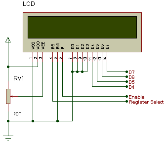

    Circuit Diagram


    D+Lock.JPG


    Here unlock output simulated using a LED


    MikroC Code:


    unsigned short kp;
    char code1[10] ,user1[4];
    char msg1[20] = "Initializing......",msg2[12] = "Enter Code";
    char msg3[15] = "Access Granted",msg4[15] = "Access Denied";
    char msg5[15] = "Enter New Code";
    int i=0,j;

    // Keypad module connections
    char keypadPort at PORTD;
    // End Keypad module connections

    // LCD module connections
    sbit LCD_RS at RB2_bit;
    sbit LCD_EN at RB3_bit;
    sbit LCD_D4 at RB4_bit;
    sbit LCD_D5 at RB5_bit;
    sbit LCD_D6 at RB6_bit;
    sbit LCD_D7 at RB7_bit;

    sbit LCD_RS_Direction at TRISB2_bit;
    sbit LCD_EN_Direction at TRISB3_bit;
    sbit LCD_D4_Direction at TRISB4_bit;
    sbit LCD_D5_Direction at TRISB5_bit;
    sbit LCD_D6_Direction at TRISB6_bit;
    sbit LCD_D7_Direction at TRISB7_bit;
    // End LCD module connection

    void code_enter()
    {
    kp = 0; // Reset key code variable
    // Wait for key to be pressed and released
    do
    //kp = Keypad_Key_Press(); // Store key code in kp variable
    kp = Keypad_Key_Click(); // Store key code in kp variable
    while (!kp);
    // Prepare value for output, transform key to it's ASCII value
    switch (kp)
    {
    case 1: kp = '1'; break; // 1
    case 2: kp = '2'; break; // 2
    case 3: kp = '3'; break; // 3
    case 5: kp = '4'; break; // 4
    case 6: kp = '5'; break; // 5
    case 7: kp = '6'; break; // 6
    case 9: kp = '7'; break; // 7
    case 10: kp = '8'; break; // 8
    case 11: kp = '9'; break; // 9
    case 13: kp = 42; break; // *
    case 14: kp = 48; break; // 0
    case 15: kp = 35; break; // #
    }
    code1 = kp;
    Lcd_Chr(2, i+1, code1); // Print key ASCII value on Lcd
    i++;
    }

    void delay_20ms()
    {
    delay_ms(20);
    }

    void code_read() //Wead data from EEPROM
    {
    delay_20ms();
    user1[0] = EEPROM_Read(0x00); // Read data from address 0
    delay_20ms();
    user1[1] = EEPROM_Read(0x01); // Read data from address 2
    delay_20ms();
    user1[2] = EEPROM_Read(0x02); // Read data from address 4
    delay_20ms();
    user1[3] = EEPROM_Read(0x03); // Read data from address 8
    delay_20ms();
    }

    void code_write() //Write data from EEPROM
    {
    delay_20ms();
    EEPROM_Write(0x00,code1[0]); // Write some data at address 00
    delay_20ms();
    EEPROM_Write(0x01,code1[1]); // Write some data at address 02
    delay_20ms();
    EEPROM_Write(0x02,code1[2]); // Write some data at address 04
    delay_20ms();
    EEPROM_Write(0x03,code1[3]); // Write some data at address 08

    }


    void change_code()
    {
    Lcd_Cmd(_LCD_CLEAR); // Clear display
    Lcd_Out(1, 1, "Enter New Code");

    i=0;
    code_enter();
    code_enter();
    code_enter();
    code_enter();
    code_write();
    code_read();
    }

    void main()
    {
    ADCON1 |= 0x07; // Configure AN pins as digital
    TRISA = 0x00; // set direction to be output
    PORTA.B0 =1;
    Keypad_Init(); // Initialize Keypad
    Lcd_Init(); // Initialize Lcd
    code_read();
    //If no code is stored then default is 2345
    if(user1[0] == 0xFF && user1[1] == 0xFF && user1[2] == 0xFF && user1[3] == 0xFF )
    {
    EEPROM_Write(0x00,'2'); // Write some data at address 00
    delay_20ms();
    EEPROM_Write(0x01,'3'); // Write some data at address 02
    delay_20ms();
    EEPROM_Write(0x02,'4'); // Write some data at address 04
    delay_20ms();
    EEPROM_Write(0x03,'5'); // Write some data at address 08
    }
    code_read();
    Lcd_Cmd(_LCD_CLEAR); // Clear display
    Lcd_Cmd(_LCD_CURSOR_OFF); // Cursor off
    Lcd_Out(1, 1,msg1 );
    delay_ms(500);
    Lcd_Cmd(_LCD_CLEAR); // Clear display
    do
    {
    i = 0;
    code_enter();
    if(code1[0] == 42)
    {
    Lcd_Cmd(_LCD_CLEAR); // Clear display
    Lcd_Out(1, 1,msg2);
    //delay_ms(500);
    i = 0;
    code_enter();
    code_enter();
    code_enter();
    code_enter();
    code_enter();
    if(code1[0] == '2' && code1[1] == '3' && code1[2] == '4' && code1[3] == '5' && code1[4] == '5') //check master code
    {
    code_enter();
    if(code1[5] == 35)
    {
    change_code();
    }
    }
    if(code1[0] == user1[0] && code1[1] == user1[1] && code1[2] == user1[2] && code1[3] == user1[3] && code1[4] == 35) //compare code with store one
    {
    Lcd_Cmd(_LCD_CLEAR); // Clear display
    Lcd_Out(1, 1, msg3);
    PORTA.B0 =0;
    delay_ms(2000);
    PORTA.B0 =1;

    }
    else
    {
    Lcd_Cmd(_LCD_CLEAR);
    Lcd_Out(1, 1,msg4 );
    }
    }
    }while(1);
    }

    Source

    Default Password: 23455
     

    fromdawest

    Member
    May 7, 2008
    17
    0
    0
    need a help in PIC programming ...

    I want to make a simple ammeter circuit using PIC16F877 . To measure the current I'm using a simple CURRENT TRANSFORMER ( 30:5 A ) . So what i want is to, get this current transformer output and make it the input to the PIC IC ( to it's ADC ), and then to drive a small LCD to show the current value .

    Please help .