MOBILE PHONE REPAIRING GUIDE

laal

Member
Apr 18, 2008
185
9
0
RF and IF Amplifiers and Filters

Electronic filters are electronic circuits which perform signal processing functions, specifically to remove unwanted frequency components from the signal, to enhance wanted ones, or both. Electronic filters can be:
Radio frequency (RF) and microwave filters represent a class of electronic filter, designed to operate on signals in the megahertz to gigahertz frequency ranges (medium frequency to extremely high frequency). This frequency range is the range used by most broadcast radio, television, wireless communication (cellphones, Wi-Fi, etc...), and thus most rf and microwave devices will include some kind of filtering on the signals transmitted or received.


SMT%20Saw%20Filter.jpg


Such filters are commonly used as building blocks for duplexers and diplexers to combine or separate multiple frequency bands.
 

laal

Member
Apr 18, 2008
185
9
0
MuItimeter Tester

What is a multimeter tester?

A multitester or multimeter is a device which can be used to gather data about electronics circuits. A basic multitester can measure resistance, voltage,current and continuity, while more advanced versions may be able to provide additional data.

Multitesters can be used with the current off or on in most cases, although using the device with the current on can sometimes result in damage to the device.This device is hand held, and powered by batteries. It consists of two probes attached to a central pack which can be digital or analog. The device has a series of buttons or switches which can be used to set the type of measurement being performed.

Analog Multitester
Analog types are been able to read manually to its Reading the needle pointing to a gauge, it requires a some computation when checking some components or where the selector is being set.
Basic Multitester has features like as follows:
Resistance Set Value: x1,
x10, = multiply by 10
x1K= it means multiply it by 1000
x10K = it means multiply it by 10,000

DC Set Value: from 0.1 to 1000 DC Voltage (Direct Current)
AC Set Value: from 10 to 1000 AC Voltage (Alternating Current)
DC Current Set Value: from 0.5micro ampere to 50 micro ampere

Continuity, the most basic measurement provided by a multitester, determines whether or not a circuit is complete. For a continuity test, the device is set to “ohms” and AC or DC, depending on the current being measured, before the probes on the device are inserted into the circuit. If the circuit is complete, the readout will measure between 0 and .05 ohms. A measurement of infinity indicates that the circuit is open, which means there is a problem.In addition to being used as a basic continuity tester,


analog%20tester.jpg

Digital Multitester

A digital multimeter is a tool that can measure amps, volts, and ohms. It is different from an analog meter, which has a needle and a gauge, in that it has a digital light-emitting diode (LED) display. Digital multimeters are typically more accurate than their old analog counterparts. A digital multimeter can also have other functions; obviously, the more expensive meters will have more features, but all of them measure the three basic currents.


digital%20tester.jpg

Another specification to consider when purchasing a DMM is its range. Regardless of what current is being tested, the proper range for that measurement is critical to the accuracy of the measurement. If the operator were testing a 12-volt battery, for instance, then a range setting of 0 to 25 volts would result in a more accurate measurement then a range setting of 0 to 500 volts. Thankfully, many DMM’s have an automatic range feature, which will set the proper range for the circuit being tested automatically; all the operator has to do is set the DMM to the proper current being tested, and the meter does the rest.

When using a DMM for the first time, it is essential that a person read the instruction manual that comes with it. Many DMM’s require different steps for taking measurements; this will entail pressing certain buttons before hooking up the leads, and so on. Most digital multimeters require a battery for operation. The instruction manual will most likely specify which type of battery to use. If the battery type is not specified, alkaline batteries are typically used.

A DMM’s maximum reading capacity is extremely important as well. This is the maximum amount of current that the meter can measure. Usually, the current limit is printed on the face of the DMM. A common limit is 10 amps. This means that if the meter is hooked up to a current of 12 amps, the internal fuse will pop to prevent damaging the meter. Installing a bigger fuse will not increase the limit of the DMM; it will only burn it out permanently.
 

laal

Member
Apr 18, 2008
185
9
0
How To Use and Read a Multimeter

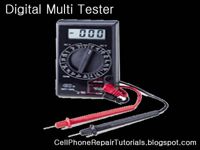
Using a multimeter is quite bit difficult for the first time especially the analog type one unlike the digital which is more convenient to use for beginners.
Every multimeter have its own user manual accompanied when you purchased it at any electronics store in your areas, and each one varies on how each circuits designed but there's always only one thing in common,
a Multimeter is is used to measure voltages AC or DC, currents and resistance, continuity and electronics components.

Maybe this only a take brief explanation on how to use a multimeter,
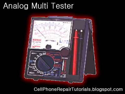
I have an example copy around here using my Sanwa analog multimeter which is made from Japan.

PARTS OF A MULTIMETER


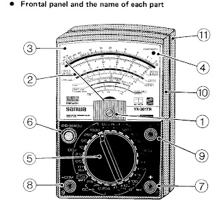
1.) Indicator Zero Connector 7.) Measuring Terminal +
2.) Indicatot Pointer 8.) Measurin Terminal - COM
3.) Indicator Scale 9.) Series Terminal Capacitor OUTPUT
4.) Continuity Indicating 10.) Panel
LED ( CONTINUITY ) 11.) Rear Case
5.) Range Selector Switch knob
6.) 0-ohms adjusting knob
/0- centering meter
(NULL meter) adjusting knob

EXPLANATION ABOUT THE SCALE

1.) Resistance ‭(OHMS) scale
2.) DCV, A scale and ACV scale
(10V or more)
3.) 0-centerig (NULL) +/- DCV scale
4.) ACV 2.5 (AC 2.5V) exclusive scale
5.) Transistor DC amplification factor
(hFE) scale
6.) 1.5 baterry test (BATT 1.5V)
7.) OHMS range terminal to terminal current
(Li) scale)
8.) OHMS range terminal to terminal voltage
(LV) scale
9.) Decibel (dB) scale
10.) Continuity Indicating LED
11.0 Mirror: To obtain most accurate readings,
the mirror is deviced to make operator eyes, the indicator pointer, and the indicator pointer reflexed to the mirror put together in line.

How to Measure Resistance

Multimeter with selector set to "Ohms". This meter only has a single Ohms range.Multimeter with selector set to "Ohms". This meter only has a single Ohms range.
Set the multimeter to Ohms or Resistance (turn meter on if it has a separate power switch). Understand that resistance and continuity are opposites. The multimeter measures resistance in ohms, it can not measure continuity. When there is little resistance there is a great deal of continuity. Conversely, when there is a great deal of resistance, there is little continuity. With this in mind, when we measure resistance we can make assumptions about continuity based on the resistance values measured. Observe the meter indication. If the test leads are not in contact with anything, the needle or pointer of an analog meter will be resting at the left most position. This is represents an infinite amount of resistance, or an "open circuit"; it is also safe to say there is the no continuity, or path between the black and red probes. Careful inspection of the dial should reveal the OHM scale. It is usually the top-most scale and has values that are highest on the left of the dial (a sideways "8" for infinity) and gradually reduce to 0 on the right. This is opposite of the other scales; they have the lowest values on the left and increase going right.

Connect the black test lead to the jack marked "Common" or "-"

Connect the red test lead to the jack marked with the Omega (Ohm symbol) or letter "R" near it.

Set the range (if provided) to R x 100.

Hold the probes at the end of the test leads together. The meter pointer should move fully to the right. Locate the "Zero Adjust" knob and rotate so that the the meter indicates "0" (or as close to "0" as possible). Note that this position is the "short circuit" or "zero ohms" indication for this R x 1 range of this meter. Always remember to "zero" the meter immediately after changing resistance ranges.

Replace batteries if needed. If unable to obtain a zero ohm indication, this may mean the batteries are weak and should be replaced. Retry the zeroing step above again with fresh batteries.

Measure resistance of something like a known-good lightbulb. Locate the two electrical contact points of the bulb. They will be the threaded base and the center of the bottom of the base. Have a helper hold the bulb by the glass only. Press the black probe against the threaded base and the red probe against the center tab on the bottom of the base. Watch the needle move from resting at the left and move quickly to 0 on the right.

Change the range of the meter to R x 1. Zero the meter again for this range. Repeat the step above. Observe how the meter did not go as far to the right as before. The scale of resistance has been changed so that each number on the R scale can be read directly. In the previous step, each number represented a value that was 100 times greater. Thus, 150 really was 15,000 before. Now, 150 is just 150. Had the R x 10 scale been selected, 150 would have been 1,500. The scale selected is very important for accurate measurements. With this understanding, study the R scale. It is not linear like the other scales. Values at the left side are harder to accurately read than those on the right. Trying to read 5 ohms on the meter while in the R x 100 range would look like 0. It would be much easier at the R x 1 scale instead. This is why when testing resistance, adjust the range so that the readings may be taken from the middle rather than the extreme left or right sides.

Test resistance between hands. Set the meter to the highest R x value possible. Zero the meter. Loosely hold a probe in each hand and read the meter. Squeeze both probes tightly. Notice the resistance is reduced. Let go of the probes and wet your hands. Hold the probes again. Notice that the resistance is lower still. For these reasons, it is very important that the probes not touch anything other than the device under test. A device that has burned out will not show "open" on the meter when testing if your fingers provide an alternate path around the device, like when they are touching the probes. Testing round cartridge type and older style glass automotive fuses will indicate low values of resistance if the fuse is lying on a metal surface when under test. The meter indicates the resistance of the metal surface that the fuse is resting upon (providing an alternate path between the red and black probe around the fuse) instead of trying to determine resistance through the fuse. Every fuse, good or bad, will indicate "good".

How to Measure Voltage

Set the meter for the highest range provided for AC Volts. Many times, the voltage to be measured has a value that is unknown. For this reason, the highest range possible is selected so that the meter circuitry and movement will not be damaged by voltage greater than expected. If the meter were set to the 50 volt range and a common U.S. electrical outlet were to be tested, the 120 volts present could irreparably damage the meter. Start high, and work downward to the lowest range that can be safely displayed.
Insert the black probe in the "COM" or "-" jack.

Insert the red probe in the "V" or "+" jack.

Locate the Voltage scales. There may be several Volt scales with different maximum values. The range chosen the selector knob determines which voltage scale to read. The maximum value scale should coincide with selector knob ranges. The voltage scales, unlike the Ohm scales, are linear. The scale is accurate anywhere along its length. It will of course be much easier accurately reading 24 volts on a 50 volt scale than on a 250 volt scale, where it might look like it is anywhere between 20 and 30 volts.

Test a common electrical outlet. In the U.S. you might expect 120 volts or even 240 volts. In other places, 240 or 380 volts might be expected. Press the black probe into one of the straight slots. It should be possible to let go of the black probe, as the contacts behind the face of the outlet should grip the probe, much like it does when a plug is inserted. Insert the red probe into the other straight slot. The meter should indicate a voltage very close to 120 or 240 volts (depending on type outlet tested). Remove the probes, and rotate the selector knob to the lowest range offered, that is greater than the voltage indicated (120 or 240). Reinsert the probes again as described earlier. The meter may indicate between 110 and as much as 125 volts this time. The range of the meter is important to obtain accurate measurements. If the pointer did not move, it is likely that DC was chosen instead of AC. The AC and DC modes are not compatible. The correct mode MUST be set. If not set correctly, the user would mistakenly believe there was no voltage present. This could be deadly. Be sure to try BOTH modes if the pointer does not move. Set meter to AC volts mode, and try again. Whenever possible, try to connect at least one probe in such a way that it will not be required to hold both while making tests. Some meters have accessories that include alligator clips or other types of clamps that will assist doing this. Minimizing your contact with electrical circuits drastically reduces that chances of sustaining burns or injury.

How to Measure Current Amperes

Determine if AC or DC by measuring the voltage of the circuit as outlined above.
Set the meter to the highest AC or DC Amp range supported. If the circuit to be tested is AC but the meter will only measure DC amps (or vice-versa), stop. The meter must be able to measure the same mode (AC or DC) Amps as the voltage in the circuit, otherwise it will indicate 0.

Be aware that most multimeters will only measure extremely small amounts of current, in the uA and mA ranges. 1 uA is .000001 amp and 1 mA is .001 amp. These are values of current that flow only in the most delicate electronic circuits, and are literally thousands (and even millions) of times smaller than values seen in the home and automotive circuits that most homeowners would be interested testing. Just for reference, a typical 100W / 120V light bulb will draw .833 Amps. This amount of current would likely damage the meter beyond repair. A "clamp-on" type ammeter would be ideal for the typical homeowner requirements, and does not require opening the circuit to take measurements (see below). If this meter were to be used to measure current through a 4700 ohm resistor across 9 Volts DC, it would be done as outlined below:

Insert the black probe into the "COM" or "-" jack.

Insert the red probe into the "A" jack.

Shut off power to the circuit.

Open the portion of the circuit that is to be tested (one lead or the other of the resistor). Insert the meter in series with the circuit such that it completes the circuit. An ammeter is placed IN SERIES with the circuit to measure current. It cannot be placed "across" the circuit the way a voltmeter is used (otherwise the meter will probably be damaged). Polarity must be observed. Current flows from the positive side to the negative side. Set the range of current to the highest value.

Apply power and adjust range of meter downward to allow accurate reading of pointer on the dial. Do not exceed the range of the meter, otherwise it may be damaged. A reading of about 2 milliamps should be indicated since from Ohm's law I = V / R = (9 volts)/(4700 Ω) = .00191 amps = 1.91 mA.

If you're measuring the current consumed by the device itself, be aware of any filter capacitors or any element that requires an inrush (surge) current when switched on. Even if the operating current is low and within the range of the meter fuse, the surge can be MANY times higher than the operating current (as the empty filter capacitors are almost like a short circuit). Blowing the meter fuse is almost certain if the DUT's (device under test) inrush current is many times higher than the fuses rating. In any case, always use the higher range measurement protected by the higher fuse rating (if your meter has two fuses), or just be careful.
 

laal

Member
Apr 18, 2008
185
9
0
How to Check Basic Electronic Components

How to Check Basic Electronic Components Using a Multi-Meter

Basic electronic components such as resistors, capacitors, diodes and transistors are widely used in any electronic devices and gadgets. Knowing how to conduct a test on this components using a multimeter would give you an idea on how to trouble shoot and repair any defective cellphones or electronic equipments at home. Below are some basic D.I.Y. regarding proper testing of this components using a multimeter.


How to Check Resistors?

Read the indicated code value indicated in Schematic Diagram then select the Ohm-scale within but not way below the indicated value. A resistor is good if its resistance is close to the indicated value.Tolerance should be considered with the ohmmeter reading. While, no resistance reading at all on the ohmmeter scale settings means that the resistor is open. A zero resistance reading on all ohmmeter scale settings means that the resistor is shorted.


How to Check Capacitors?


In most cases, a capacitor fails due to the deterioration of the dielectric material between its plate.Defective capacitors can have an internal shorted terminals, excessive leakage and degradation of capacitance meter. For an electrolytic capacitor (capacitors with polarity), short the terminal capacitor to discharge it prior to testing.

To test a capacitor, set the multimeter to Rx10 or Rx1K scale. Connect the tester negative probe to the capacitor positive terminal and the positive probe to the negative terminal.

A good indication for electrolytic capacitor shows the meter needle deflecting towards zero and moves back again to infinite resistance position.
For ceramic, Mylar and other capacitor with a capacitance with less than 1.0 uF, the meter will not deflect at all.

A defective indication for an electrolytic capacitor shows that the meter will rest on zero and remain stationary at a point which is an indication that the capacitor is shorted.

How to Check Diodes?


Set the multimeter knob to any of the resistance position (x1, x10, x1K or 10K ohm ).Connect the positive probe to the anode and the negative probe to the cathode.Then connect the positive probe to the cathode and the
negative probe to the anode of the diode. A good indication in the first procedure will show the meter deflected very little or may not deflect at all.

And in the second procedure, the meter will deflect towards zero.The actual resistance reading is the forward resistance of the diode.

A defective indication shows that the meter won't deflect at all even when the probes are reversed. Or the meter deflects at the same time or almost the same resistance reading for both steps.

How to Check Transistors:


Bipolar transistors are usually checked out of a circuit by means of an ohmmeter. When it is desired to check for the resistance across the transistor emitter and collector, NPN or PNP, ohmmeter probes may be connected either way. A good transistor will show above a reading above 1000 ohm.

How to determine if it is NPN or PNP transistor?

To determine the correct terminal of the transistors, set the range selector to x 1 or 10 ohm.Connect the positive probe to the emitter and the negative probe to the base of the transistor. Note the reading interchange the connection of the probes to the leads of the transistor.

Base your conclusion on the table:

POSITIVE PROBE TO: -----NEGATIVE PROBE TO: -----RESISTANCE READING-- CONCLUSION:
Emitter------- -- Base---------- Less than 150 ohm ------Transistor is NPN
Base --------------Emitter --------Infinity ----------------Transistor is NPN


POSITIVE PROBE TO: NEGATIVE PROBE TO: RESISTANCE READING: CONCLUSION:
-Emitter------------Base ---------Infinity ---------------- Transistor is PNP
Base --------------- Emitter --- - Less than 150 ohm ------- Transistor is PNP

Some defective indications of transistors: Resistance between any pair of the terminals is less than 10 ohms, means that the transistor is shorted. Resistance between base and emitter or base collector for both the forward and reverse application of ohmmeter probes is infinity (meter needle don't deflect), means that the transistor is open. Transistors overheats (except power transistors) during normal operating condition means that the transistor is shorted.


How to Check an LED ( Light Emitting Diode)

Set the Muti-meter to x1 connect the positive probe to cathode and the negative probe to anode. The good and working LED will then light up or glow, a busted LED will not.


How to Check a Coil?

Set the multimeter to X1 a good and working coil have a reading approximately point to zero ohms, without any reading means the coil is open or busted.


How to Check a Fuse?

A blown SMD Fuse is not visible to our naked eye, just set the multi-meter to x1 and put both test probe to both end side of the fuse. A full reading here to zero or continuity check is full. without any reading means the fuse is already busted.


How to Check IC chips (Integrated Circuits)?

IC Chips is hard to determine faulty by using only a multi-meter, some advance equipment like the one that the manufacturer used during their productions. However; you can determine a faulty chips by some few experiences when it comes to troubleshooting, One techniques is that by comparing two same components from one another. like for example; if one chips is suspected to be faulty, then by replacing it with a good and working same chips, you can now determine it if the said chips got a problem. It is a trial and error method at first; but as long as your experience and knowledge skills increases, you can determine it more quickly and accurately.
Further, we will tackle this issues and give you some tips and tricks
 

laal

Member
Apr 18, 2008
185
9
0
Opening Tools and Tweezers

Opening Tools

Proper opening tools is used to avoid damaged and insure safety in handling mobile phones, which prior to avoid risk of scratches and breakage.

opening%20tools%201.jpg

Tweezers
Tweezers are tools used for picking up small objects that are not easily handled with the human hands and very useful in surface mounted electronics components.
tweesers.jpg

Torx and Precision Screwdrivers
Various Mobile phone uses variety of screws mounted to every products.
screw%20opener.jpg
Do not try to attempt opening any screws that did not match with the screwdriver you have or you might end up a loosen tread screw, and find it hard enough to open it up...
Selecting and collecting of Torx and precision screwdrivers is highly recommended.
Torx and Precision comes with different code and number..
T6 is the most commonly used in mobile phones
 

laal

Member
Apr 18, 2008
185
9
0
Soldering and Desoldering Tools

Soldering Iron
A soldering iron is a tool normally used for applying heat to two or more adjoining metal parts such that solder may melt and flow between those parts, binding them securely, conductively and hermetically.

soldering%20Station.jpg
A soldering iron is composed of a heated metal tip and an insulated handle. Heating is often achieved electrically, by passing an electrical current (supplied through an electrical cord or battery cables) through the resistive material of a heating element. Another heating method includes combustion of a suitable gas, which can either be delivered through a tank mounted on the iron (flameless), or through an external flame.

soldering%20smd.jpg
Some soldering irons heat up and cool down in a few seconds, while others may take several minutes.


Soldering LEAD
Soldering lead is used to bond or connect electronic components.
Solder is a fusible metal alloy with a melting point or melting range of 90 to 450 degree Celsius (190 to 840 °F), used in a process called soldering where it is melted to join metallic surfaces. It is especially useful in electronics . Alloys that melt between 180 and 190 °C (360 and 370 °F) are the most commonly used. By definition, using alloys with melting point above 450 °C (840 °F) is called brazing. Solder can contain lead and/or flux but in many applications solder is now lead free.
soldering%20lead.jpg

While it is possible to do some wiring without soldering connections, soldering is the preferred approach. Proper soldering is easy with the right tools and techniques. One item that is critical is the right solder. DO NOT use the environmentally friendly lead free solders, they don't work worth a damn. Even in carefully controlled industrial conditions, lead free solders produce inferior connections. As much as the politicians backed by environmentalists would like to, they can't legislate metallurgy.

Soldering Paste
Solder paste (or solder cream) is used for connecting the terminations of integrated chip packages with land patterns on the printed circuit board. The paste is applied to the lands by printing the solder using a stencil, while other methods like screening and dispensing are also used. A majority of defects in mount assemblies are caused due to the issues in printing process or due to defects in the solder paste. An electronics manufacturer needs to have a good idea about the printing process, specifically the paste characteristics, to avoid reworking costs on the assemblies.
soldering%20paste.jpg

Characteristics of the paste, like viscosity and flux levels, need to be monitored periodically by performing in-house tests.

Soldering flux Soldering flux is just a safe, convenient acid for dissolving the oxide skin off the metal
you want your solder to wet well. Also dissolves oxide off the liquid solder, making it
less crusty and therefore more shiny.
soldering%20flux.jpg

"Acid" flux is the stronger class of flux; it has something like hydrochloric acid in
it. (The paste form has zinc chloride.)
This is good for making difficult oxides dissolve so difficult metals like stainless
steel can be solder-wetted.
But the acid can hang around later trying to corrode the metal it just cleaned for you.
So for electronic stuff we mostly do not use it.
If we do, we scrub it off with things like toothbrush, water, soap, alcohol, baking soda,
to minimize acid residues.

The flux built into most solder wire is called rosin flux.
I think it is an organic acid (so is vinegar, and tart-tasting "citric acid"),
stuck onto larger molecules that melt only at soldering temperatures.
That is the clear yellow-brownish plaque that sits on the solder's surface when you are
done.
It does the same stuff as acid flux, but it is milder two ways.
It is only strong enough to reduce weakly oxidizable metals like copper, tin, lead,
silver.
So it is just strong enough for electronics use, but not for soldering to stainless
steel or iron or anything with chrome or aluminum.
And rosin-flux goes back to its plastic-like solid form after use, so it does not act
very corrosive to the metals later on.
So we do not need to clean it away carefully.
It can be cleaned away if you want to work at it, with brush-scrubbing and the right
"polar solvents".
"Flux remover" is sold in spray-cans for this. Rubbing alcohol with a dash of dish-soap
sort of works for me.
Try it and see what it looks like.


Soldering Wick
A solder wick (also desoldering wick or desoldering braid) is a tool for removing solder from any solder joint. Usually, it is a roll of fine, braided 18 to 42 AWG wire, typically oxygen free copper, which has been treated with a rosin solder flux.

desoldering%20wick.jpg


Close up to a piece of solder wick


Close up to the netting of a solder wick


To remove solder with it, one presses the wick onto the solder joint to be removed and then heats the wick portion that is on the connection with the tip of a soldering iron. As the rosin melts onto the wick and the connection and the solder reaches its melting point the solder rushes via capillary action onto the clean copper braid. Once everything has melted and the solder fuses with the braided copper, the wick is lifted along with the solder and is then cut off and disposed of.
 

laal

Member
Apr 18, 2008
185
9
0
SMD Rework Stations

SMD(Surface Mounted) Rework station is used to remove, replace, do re-balling BGA(Ball Grid Alley) chips and SMD components.
Make sure that the re-balling station are controllable and match to standard temperature for PCB's and SMD Electronic Components..
It is made of high quality heating material. desoldering and soldering of BGA's are precisely controlled.
Air flow and and Temperature are adjustable in wide range to produce high temperature breeze.
Movable and Replaceable heating heads and very easy to operate...


Rework%20Stations.jpg

In the market today there are two types of rework station to choose that match your needs and budget.
The Oldest type is the Standard Filament Type Rework Station and the latest is called Infrared or IRDA Rework Station.
The Standard Type is Consist of a heating filament which is by then blowned by an air to produce a very hot air temperature.

A technical view of an SMD Rework Station with filament and an air blowing to produce hot temperature air flow...

hot%20air.gif

Thermostat adjustment is applied by controlling the heat temperature and the amount of air to flow.
SMD%20analog.jpg
Some types of Filament SMD Rework Station are digital in which the amount of heat and air were displayed on a seven segment LED and a push button adjustment were placed.
SMD%20digital.jpg

Infrared or IR SMD Rework Station
This one was designed by an Infrared (IR) Technology.Uses infrared heat wave technology instead of the conventional hot air, effectively solves the major problem being encountered when using the hot air gun, which is the movement of surrounding components while reworking.
The small amount of Infrared light is amplified to produce a very high temperature Lazer Beam. It is digitally designed and can be set automatically.

A simple overview of an IR SMD Rework Station.
SMD%20basic.gif


A set example of an IR SMD rework Station. Note: the Author is not endorsing any product.
SMD%20ir.jpg
 

laal

Member
Apr 18, 2008
185
9
0
DC Power Supply

Adjustable DC Powers Supply
The Dc power Supply can be used to substitute for the Battery Voltage when do live voltage checking on the PCB circuits... This is being used to trace the power supply line in electronic circuit.

a%20dc%20power%20supply.jpg
Linear Adjustable DC Power Supply is a equipment with high stability, high reliability, low noise, its output voltage or current can be continuously adjusted, and its constant voltage and current can auto-conversion. This universal power supply can be used in many different areas, from test of R&D equipment to test of production lines.

Here's a sample of substituting DC voltage in working cellphone repair tracing B+ line.
dc%20power%20supply.jpg
 

laal

Member
Apr 18, 2008
185
9
0
Cleaning Tools

Cleaning kits and tools is also necessary when repairing specially when working wet units, corroded or rusted PCP boards. Some cleaning tools may found at household or home products and not so hard to find and prepare it. here's; some cleaning tools that may you find at home.

Brushes can help eliminate and wipe dust on PCB Components.Make sure that the brushes you may use have low electrostatic ability.


paint%20brush.jpg


tootbrush.jpg


brushs.jpg

A cotton cloth or sponge and cotton buds which help to wipe extra solvents, dust,rust and dirt.


cotton%20cloth.jpg


sponnge.jpg

Anti Static Spray or liquids used to eliminate water residues and corrosive element in PCB component.
stic%20cleaner.jpg

A lacquer thinner is a substitute to anti static cleaner and commonly and widely used by many technician's.

lacquer.jpg

An Ultrasonic Cleaner- A machine that cleans by using a fluid that is vibrated at 20,000 cycles per second. When the vibration speed rises above the ultrasonic frequency level, bubbles explode and generate strong power, cleaning the surfaces and cavities of hard-to-clean objects.
ultrasonic.jpg
 

laal

Member
Apr 18, 2008
185
9
0
Reballing Kits

Re-balling kits are used to repair broken or weak soldered BGA (Ball Grid Array) Chips.
This is very important tools when it comes to hardware problem troubleshooting in various mobile phones.
This is only being used when an IC or chips was being suspected having fault or causes the problem.
That is because Mobile phones used BGA (ball grid array) solder balls that holds as connection terminal of every chips.


There are many kits you can buy via online this days unlike before that most of mobile phone technician was unable to used this kits for it was not too easy to find and purchase. The process is that they just remove the entire solder balls and flattened out the entire bump terminal then replace the chips again. It may work but not totally effective as like for my years experience for the soldering process is too weak and easy to break , because the amount of soldered balls that holds the chips is not strong enough to hold it.
Althought reballing IC's is not that easy for beginners to tackle to. it needs training and proper procedures to follow, further we will discuss the easiest way on how to reball IC chips.


These are the kits you must prepare to be able to proceed in reballing BGA chips.

A Solder Balls
Solder balls have different sizes and measured by diameter,that match on every chips bumps sizes also.
These are the common Soldering Ball diameter ranges for mobile phones chips.
0.05, 0.10, 0.15, 0.20, 0.25mm, 0.30mm, 0.35mm, 0.40mm,0.45mm,0.50mm ,0.55mm ,0.60mm, 0.65mm, 0.76mm


A BGA Stencil Pattern Plates
This is being used to properly align the solder ball on every bumps of the chips.

every chips have different bumps pattern and alignment designs.


Spatula
this is used to gathered the solder ball on each holes of the Stencil plates.


A liquid Flux


A PCB Board Holder
a PCB holder is being used to maintain the accuracy while working soldering and to avoid gripping and misalignment of solder balls.

A Cleaning liquid
Too many cleaning product offered today that is non flammable.
A lacquer thinner will work, and still widely used for many mobile phone technician.


A cotton buds


A Brush


laal

Member
Apr 18, 2008
185
9
0
Safety Procedures and Proper Handling of Tools and Test Equipments on Cellphone Repai

Safety procedure and proper handling of tool is highly observed when working any electronic components to avoid risk of unnecessary further damages whatever you are working at. These are the following thing that always to remind when working any electronic components such as cellphones.

Antistatic Wrist Strap

Wear a Ground Strap.
Anti static wrist strap is used to avoid risk of electrostatic discharge from a human body to an electronic component circuit.
An antistatic wrist strap, ESD wrist strap, or ground bracelet is an antistatic device used to prevent electrostatic discharge (ESD) by safely grounding a person working on electronic equipment.

It consists of a stretchy band of fabric with fine conductive fibers woven into it. The fibers are usually made of carbon or carbon-filled rubber, and the strap is bound with a stainless steel clasp or plate. They are usually used in conjunction with an antistatic mat on the workbench, or a special static-dissipating plastic laminate on the workbench surface.

Hand Gloves
You are not just protecting your hand from posibble burns or brushes. it also protect the cellphones from scratches and possible electrostatic discharge. A cotton cloth made glove is essential to use.


Safety Handling with Rework and Soldering Stations
Rework and soldering Station is a hot surface devices and can cause fire instanly and extreme burns on skin when unproperly handled.
Always Observe and Set it in proper heat and air flow amounts.

SMD%20analog.jpg
Secure a safe place on your table where the rework station is located. Avoid inplacing it that people may pass or standing by especially kids.


Always shut it off when not in use and place unto the holder stand to avoid risk of fire and skin burns.


Safety Handling of a Multitester

a multitester may damaged easily when unproperly handled. always check ranges when checking voltages and currents. The deplection yoke of the analog meter may be bust out when overdrive by a current to it.
analog%20tester.jpg

Measuring Resistance

Set the multimeter to Ohms or Resistance (turn meter on if it has a separate power switch). Understand that resistance and continuity are opposites. The multimeter measures resistance in ohms, it can not measure continuity. When there is little resistance there is a great deal of continuity. Conversely, when there is a great deal of resistance, there is little continuity. With this in mind, when we measure resistance we can make assumptions about continuity based on the resistance values measured. Observe the meter indication. If the test leads are not in contact with anything, the needle or pointer of an analog meter will be resting at the left most position. This is represents an infinite amount of resistance, or an "open circuit"; it is also safe to say there is the no continuity, or path between the black and red probes. Careful inspection of the dial should reveal the OHM scale. It is usually the top-most scale and has values that are highest on the left of the dial (a sideways "8" for infinity) and gradually reduce to 0 on the right. This is opposite of the other scales; they have the lowest values on the left and increase going right.


Mesuring Voltage Ac-DC

Set the meter for the highest range provided for AC or DC Volts. Many times, the voltage to be measured has a value that is unknown. For this reason, the highest range possible is selected so that the meter circuitry and movement will not be damaged by voltage greater than expected.

Measuring Current by Ampere

Set the meter to the highest AC or DC Amp range supported. If the circuit to be tested is AC but the meter will only measure DC amps (or vice-versa), stop. The meter must be able to measure the same mode (AC or DC) Amps as the voltage in the circuit, otherwise it will indicate 0.
digital%20tester.jpg
Be aware that most multimeters will only measure extremely small amounts of current, in the uA and mA ranges. 1 uA is .000001 amp and 1 mA is .001 amp. These are values of current that flow only in the most delicate electronic circuits, and are literally thousands (and even millions) of times smaller than values seen in the home and automotive circuits that most homeowners would be interested testing. Just for reference, a typical 100W / 120V light bulb will draw .833 Amps. This amount of current would likely damage the meter beyond repair. A "clamp-on" type ammeter would be ideal for the typical homeowner requirements, and does not require opening the circuit to take measurements (see below). If this meter were to be used to measure current through a 4700 ohm resistor across 9 Volts DC, it would be done as outlined below:

Safety Handling of a Power Supply
Power supply may also damaged and cause damaged to a component..
a%20dc%20power%20supply.jpg
Always set it and determine the correct amount of Voltage range to avoid risk of blowing out any electronic parts.

Do not short the two alligator clips because the power supply will heat up and may busted out the protection fuse.
 

laal

Member
Apr 18, 2008
185
9
0
How to Read Cellphone's Schematic Diagrams

How to Read Cellphone's Schematic Diagram?


Schematic Diagram is a layout of symbols and and connection of every electronic components circuit where serve as a guide on how the circuit function or work.
Reading Schematic Diagrams is not a hard task to do, schematic diagrams is a big help to cellphone-repair
especially when working on or tracing lines and finding where a particular components mounted on a PCB board.
Such schematic diagrams is very useful and very important guide in every cellphone technician. It is equivalent to a handbook.
Learn how to read it. At first you might think that it is hard to do so, You are not going to be an experts and master in cellphone repair as long as you don't know how to read it. Many among cellphone repairman exist nowadays that do not have any knowledge about reading it. They always rely on finding free solutions over the internet and forums. Those people who give free solutions are those people who knows how to read a schematic diagram. Now here's your chance to learn and do not rely unto others, and be an expert and master troubleshooter when it comes to hardware problems.

Okay here's a step on how to read a schematic diagrams.

1. You need to download service Schematic Diagrams, as many or complete package in every cellphone products. each unit of a product have specific service diagrams.

2. You need to download Adobe Acrobat Reader so that you can open the schematic file which is in PDF format.

Now assuming that you already have those I've mention above; Let's try to open up one file like for example we are going to open a schematic diagram of Nokia N70.

here's what it looks like when scrolling down all the pages.
Let's take a little brief on each page for simple understanding..


A. page 1, In this page where you can find and Identify the whole assembly of the unit.
this is also where to findd the table of contents of the entire circuit's layouts.


warning.gif


B. page 2, In this page is a block diagram of an RF and Baseband: this is a basic explanation of the entire connection of a circuit. It was called a block diagram for it is being drawed into blocks.

What is a BASE BAND?
In telecommunications and signal processing, baseband is an adjective that describes signals and systems whose range of frequencies is measured from zero to a maximum bandwidth or highest signal frequency; it is sometimes used as a noun for a band of frequencies starting at zero. It can often be considered as synonym to lowpass, and antonym to passband, bandpass or radio frequency (RF) signal.

What is a RF?
Radio frequency (RF) is a frequency or rate of oscillation within the range of about 3 Hz to 300 GHz. This range corresponds to frequency of alternating current electrical signals used to produce and detect radio waves. Since most of this range is beyond the vibration rate that most mechanical systems can respond to, RF usually refers to oscillations in electronics circuits.

warning.gif


C. page 3, here we can find the system connectors and parts of the unit that correspond to the user or outer parts such us headset, charger and USB connection interfaces.

warning.gif


D. page 4, The power management circuit, audio codecs and drivers and the interfaces like the microphone, earpiece, mouthpiece, vibrator, sim-card, battery connections. This is the Power Supply Area of the entire circuits.

warning.gif


E. page5, Charging Control and Flash Interface Circuit.

warning.gif


F. page 6, This is the part of the circuit where the all application is being process, Flash IC and memories, this also where application and firmware are being stored.

warning.gif


G. page 7, his the Central processing of the unit (CPU) like the personal computer (PC) cellphone also have a CPU to process applications and software.

warning.gif


H. page 8, A Frequency Modulation (FM Radio) circuit.

warning.gif


I. page 9,This page is the part of an LCD Display and Keypad circuit.

warning.gif


J. page 10, this is the RF components circuit, In this page the RF or the process of a network during Transmitting and Receiving Radio Frequency signals.

warning.gif


K. page 11, This the structure of the whole PCB Board and all the components mounted in the entire circuit.
this is also where pattern of test-points for check-up during production and servicing.
at the right side is the pattern of waves of frequencies as a guide by using an oscilloscope, frequency generator and spectrum analyzer.

warning.gif


L. page 12, This is where the table of each and every components is mounted on the PCB board written in codes, like Rxxx - resistorr, Cxxx - Capacitor and etc.
The right side is the scale pattern of every components for quick and easy finding it.

warning.gif


that was only the brief explanation of every pages of an Schematic Diagram. Further we will tackle on it even deeper.
 

laal

Member
Apr 18, 2008
185
9
0
Understanding Keypads Circuit, a way to Learn How to Repair Keypad Problem

Understanding the Keypad circuit may help and boost your knowledge on fixing keypad problem issues on mobile phones. Keypads is a part of user interface being used to navigate or enter numbers, letters and characters, browse application, sends information and etc.

An schematic diagram below will help us understand how keypad circuits works and which components or parts did this circuit is being connected.
In this diagram the each and every key switching pads is being divided and grouped into rows and columns. Each rows and columns were group into 2 -5 keypads switch. This rows and columns have each corresponding lines according to each and every group of switching pads.


This lines of rows and columns is being filtered for EMI and ESD protection the EMI filter is made of tiny chip that used to protect such EMI and ESD interference.
This rows and columns lines are digital switching signals generated by the application processor to trigger or activate every corresponding digital datas that is being stored and programmed within the mobile phone system memory. This diagram below is an Application Processor that generates and feeds then receives digital data switching signals.
This digital data frequency signals corresponds and interpreted to each key characters that are marked on each keypads. Like for example a combination of row 2 and column 3 will triggered the number 3 when hitting on it.
this block diagram below shows how the switching signal is being triggered to process a command data.
Various mobile phones have different keypads layouts and specification. A joystick and a volume switch is also parts of keypads switching circuits. Some keypads module designs are made into a flexible wire like those Slide Type package of mobile phones. Some flexible wires are very vulnerable and common cause of keypad malfunction.
 

laal

Member
Apr 18, 2008
185
9
0
How Do LED light bulbs works on Mobile Phone Circuit

An LED - light emitting diode is used to illuminate keypads keys and LCD screen displays on all mobile phones handsets. It is being controlled by a voltage or current draws on its terminal leds.
a picture below is an Schematic Diagram that tells us how does the LED circuit works on cellular phone whole circuitry.

On schematic diagram we notice that the LEDs is driven by an LED driver chip's, and an Switching Control circuit that also being packed in a chip. The LED driver is being used to stabilized the voltage and current and do take control on engaging ON and OFF status of an LEDs to light up or not.
It also drives the amount of brightness or dimming status of the LEDs by applying Pulse Width Modulation signal from the Switching control circuit.

The block diagram below interpreted a component and section or parts of an LED circuit to work during application process.
The Switching control circuit feeds and release a Pulse Width Modulation Signal (PWM) to switch and light up the LEDs light bulbs. A pulse width modulation signal is a type of digital frequency signal range up to 1khz to enable and implement to take control of LED brightness.
Once that certain signal is being received by the LED driver, the LED driver now will engage and release the voltage or current that being feeds up from the mobile phones battery supply voltage;
The output voltage release by the LED driver is the one that draws the LED light bulbs to light up.


LED drivers is a high frequency, synchronous boost converter with constant current output to drive up to 5 white LEDs. This device circuit is designed for maximum safety, it integrates overvoltage and short circuit protection when the output is being shorted to the ground. Meaning this chips circuitry will not easily breakdown for it is designed to protect when short circuit happens.
like for example, the two LED light bulbs commits short circuit to its terminal
In mobile phones application methods; the switching control circuit that release pulse switching signal is also being synchronized programmed by the the application processor (CPU) to engaged a full control on how and which proper situation that the LED will be switch to light up or not.
like for example the LED will only switch and light up, if the handset is being in used and remain off if the handset is not in used.
The above image is an example of the LED circuit, how those particular stages and components being mounted on a phones circuits. Note that the LED driver and switching control circuits is being packed into an Integrated Circuit or ICs.


To all beginners: A bunch of simplified STEP By STEP Procedures On Troubleshooting LED Problem issues on various mobile phones product will be Posted Here Later.. Just keep on visiting this blog more often.
 

laal

Member
Apr 18, 2008
185
9
0
How Do SIM Card Works on Mobile Phones Circuit

A SIM Card also known as Subscriber Identity Module, A SIM is a Smart Card that can store data from a cellular phone. Those data like identity, location and phone number, network authorization data, personal security keys, contact lists and stored text messages. Security features include authentication and encryption to protect data and prevent eavesdropping.

But how does this SIM card works within the mobile phones circuit? How does mobile phones reads and write data unto it?
In those particular questions above, If we learn answers unto it, we can solve problem issues regarding SIM related problems, like Insert Sim Card and etc.

Now here's a brief explanation on how does SIM Circuit Works on a mobile phones circuit.

A Sim Card have six pads that also corresponds to the six SIM connectors pins, but only five has totally have connection on the entire layout.
SIM DATA - this is a digital data that being stored on a SIM memory
SIM Clock - this is a clock frequency signal that being synchronize to the digital data to create data signal in order transfer or sends and receive data information.
SIM Reset - this is also a frequency signal that triggers or reset all synchronization process.
VSIM B+ Supply Voltage- This a power supply voltage used to activated the SIM circuit.
SIM Ground - a ground line voltage
The other one is not connected


A Typical block Diagram above shows on how SIM Circuit Works on a Cellular phones circuits.
In the layout the Sim Interface Connector connected directly to SIM Control Circuit. The SIM Control Circuit is the one the generates Clock frequency that triggers the SIM data storage, once the SIM is now being triggered, it is then now sends data information to the application processor to begin the process with. The application processor is the one that gathered all data information from the SIM memory, initiate and activate it, if all information is in desired status.
Those three particular lines of signal flows associated in the circuit shows how the synchronization is being applied. If one of those lines being cut off the sending and receiving process will breakdown, and will result to SIM problem issues. The Power Supply Voltage through the SIM is also remain stable otherwise a lack of voltage will not activate the SIM to work.


In a picture below an EMI-ESD Filter has been added to protect the circuit to an Electro-static Discharge and Electro-magnetic Interference disorders. This type of SIM connection circuit is an advantage to mobile phone technician for troubleshooting SIM related problem issues. Thus, type of particular EMI filter is very vulnerable and mostly create breakdown to the entire SIM connection.
The picture below is an equivalent layout of an EMI filter and its internal circuitry,
only both frequency and data lines is being filtered.
The EMI Filter is a tiny chips designed to protect SIM DATA, SIM Clock and SIM Reset data signals that flow across trough the SIM connector.
The EMI-ESD Filter is a highly integrated device designed to suppress EMI(Electromagnetic Interference) and RFI(Radio frequency Interference in a circuit. This filter includes ESD protection circuitry which prevents damaging the mobile phone application when subject to ESD ( ElectroStatic Discharge) surges up to 15 kV.

Here's an example of how the the SIM data signal flow across the printed circuit board.
Note: this is only shows where the signal flows from component to component connections.


A picture above is an alternative way by many mobile phone technician dealing with SIM problem issues on most Nokia Mobile Phones.