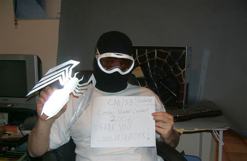
This is the case that won Coolermaster contest 2006.Creator is Brian carter who is very famous for his boeing 747 pc mod and monitor in PC mod.
this isa copy paste from his site.This is named as mystique as it features a mystique 631 case.A very valuable casing.
MYSTIQUE²


STORY:
I came up with the idea to create one HTPC desktop-style case using two Mystique 631 aluminum tower chassis. The main idea was to keep evident the Mystique heritage and styling throughout the case, inside and out. The wavy theme was carried out in tandem with logo elements to create a consistent and elegant look, while keeping its ultimate use in mind. This being a home theater PC, it will be located in my living room, and must function as a HDTV tuner/personal video recorder. Care was taken when selecting components that were best suited for such a task (i.e. Mars cpu cooler running in silent mode).
System Specs:
Asus A8N SLI Premium Motherboard
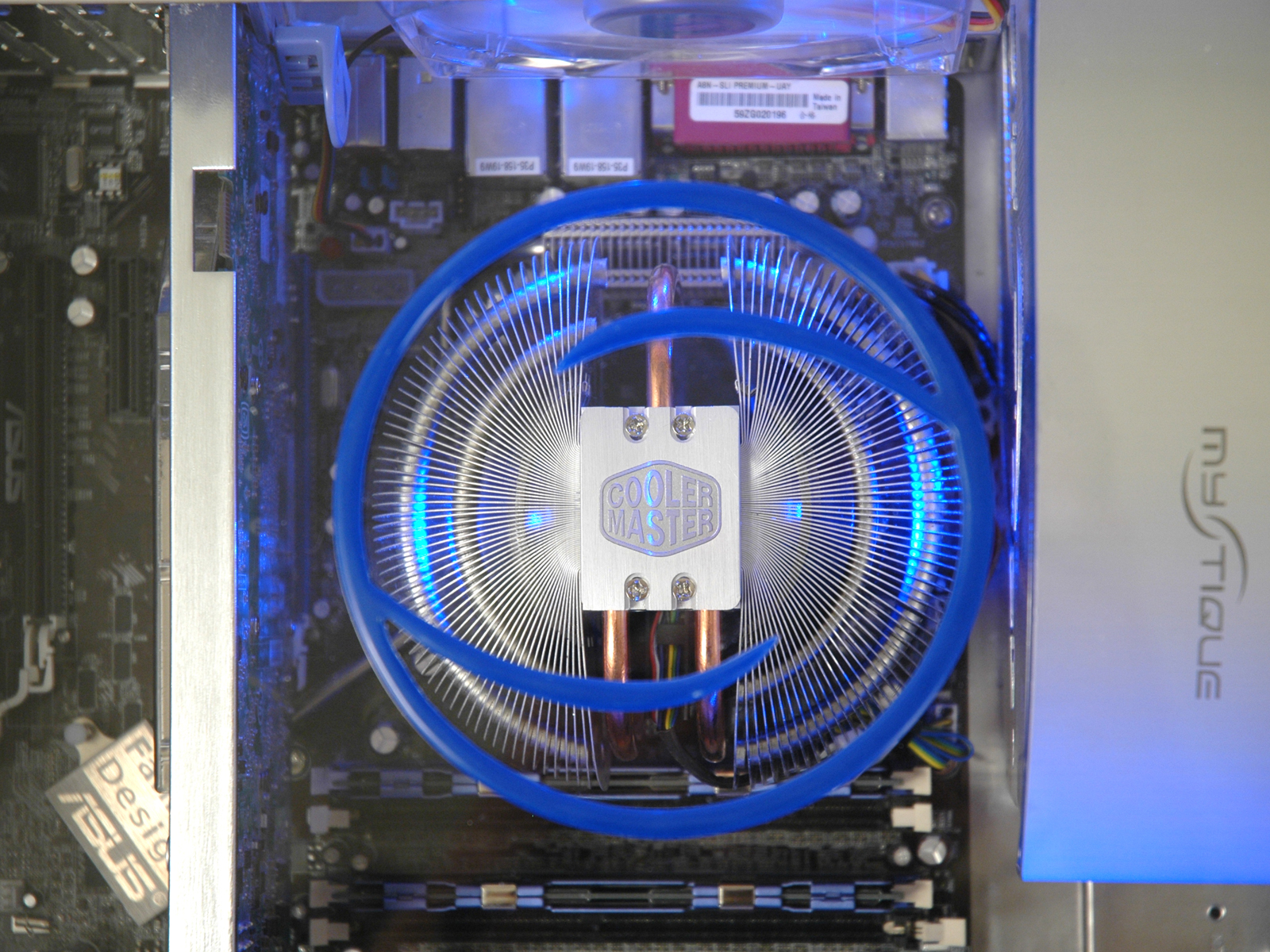
AMD FX-55 cpu with CM Mars cooler
Centon PC-3200 RAM (1Gb)
Geforce XFX 7800GT Video Card
Sound Blaster Audigy Sound Card
Western Digital SATA 200Gb Hard Drive
Cooler Master 600W eXtreme Power PSU
Pioneer Slim-line Slot Loading DVD drive (x2)
WinPVR Tv-tuner PCI card
Cats Eye HDTV tuner PCI card
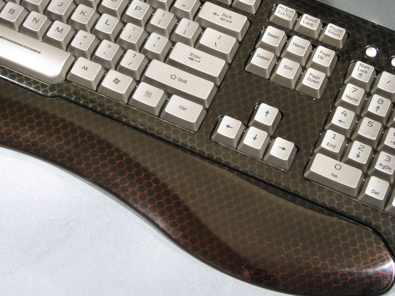
Zippy Aluminum Keyboard
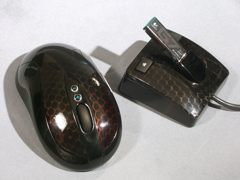
Logitech Cordless Mouse
iDuo 10-in-1 Card Reader/iPod Dock
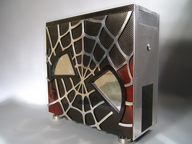
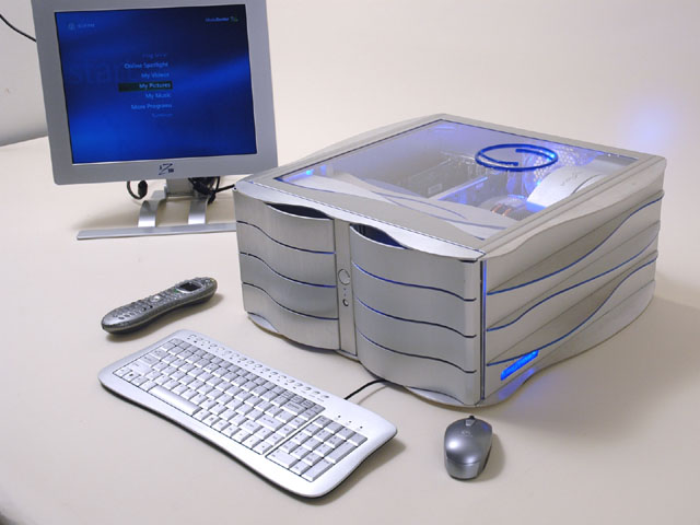
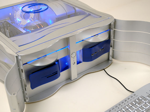
I wanted to design the case in such a way as to make people immediately think "Mystique" when they first see it.


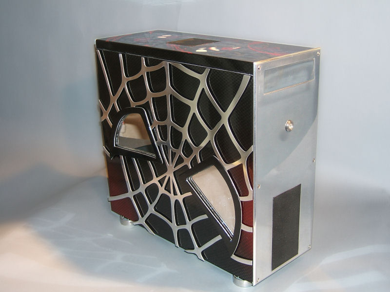
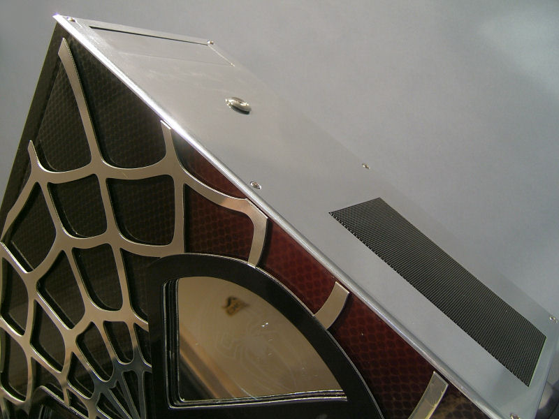
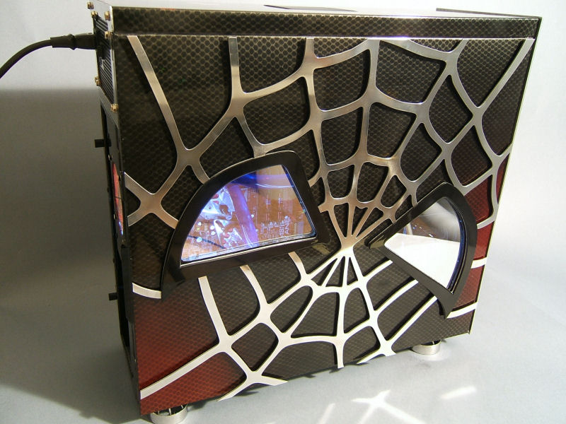
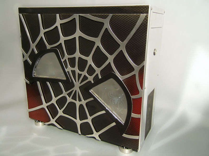
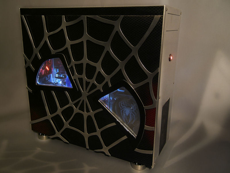
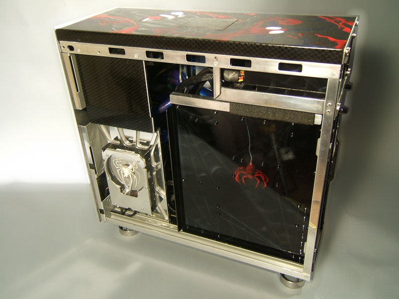
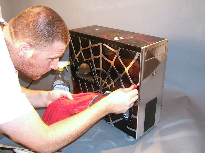
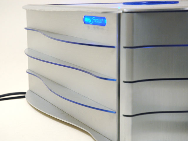
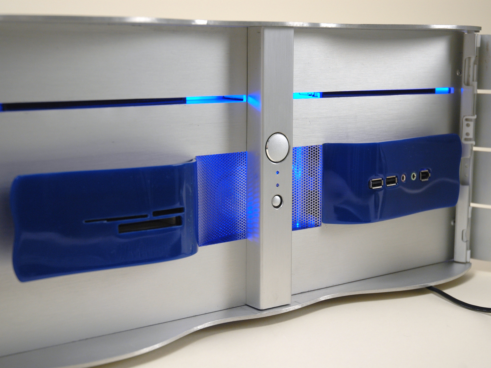
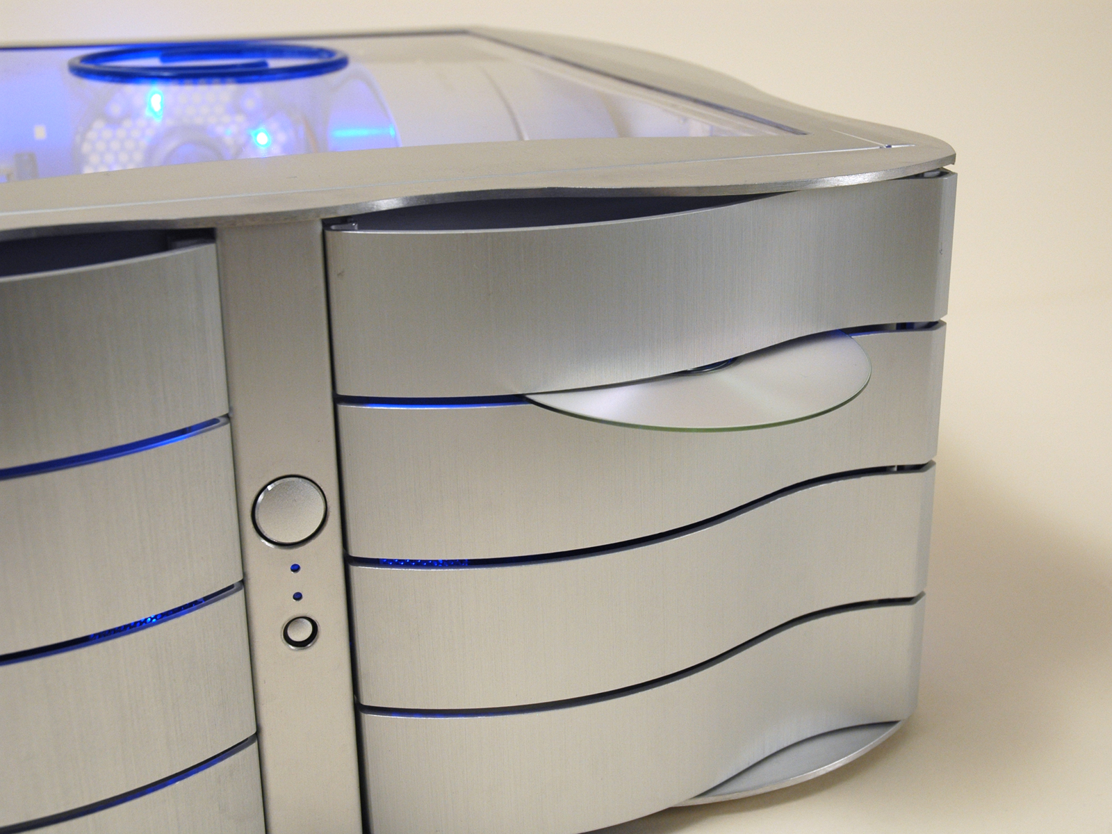
The Mystique's signature front wavy doors were retained, and aluminum fins were added on both sides and aligned with the doors' slots, continuing the wavy theme around the case.

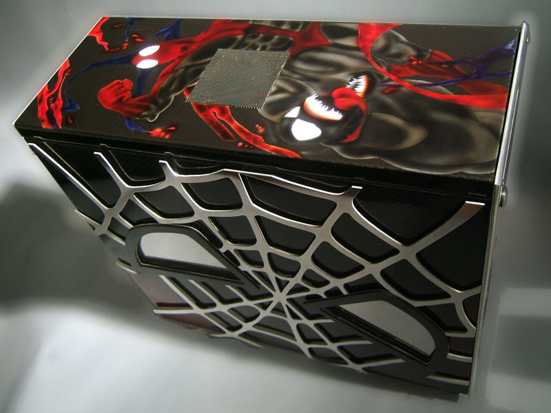
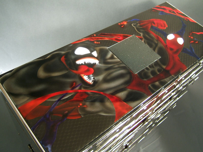
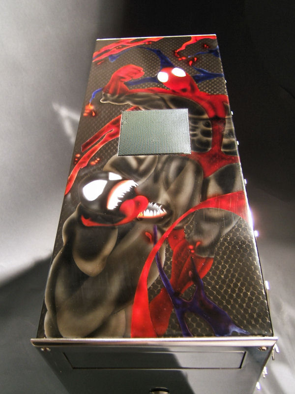
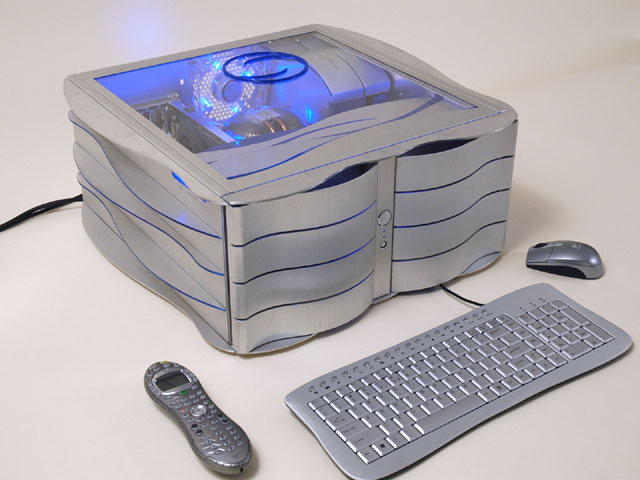
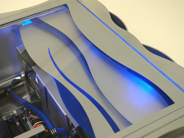
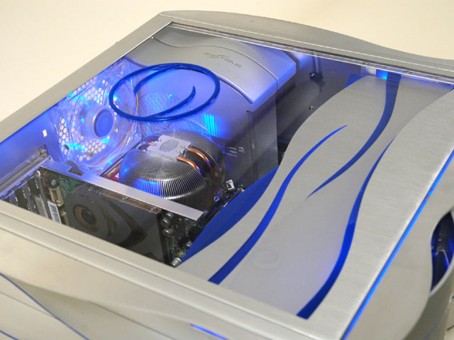
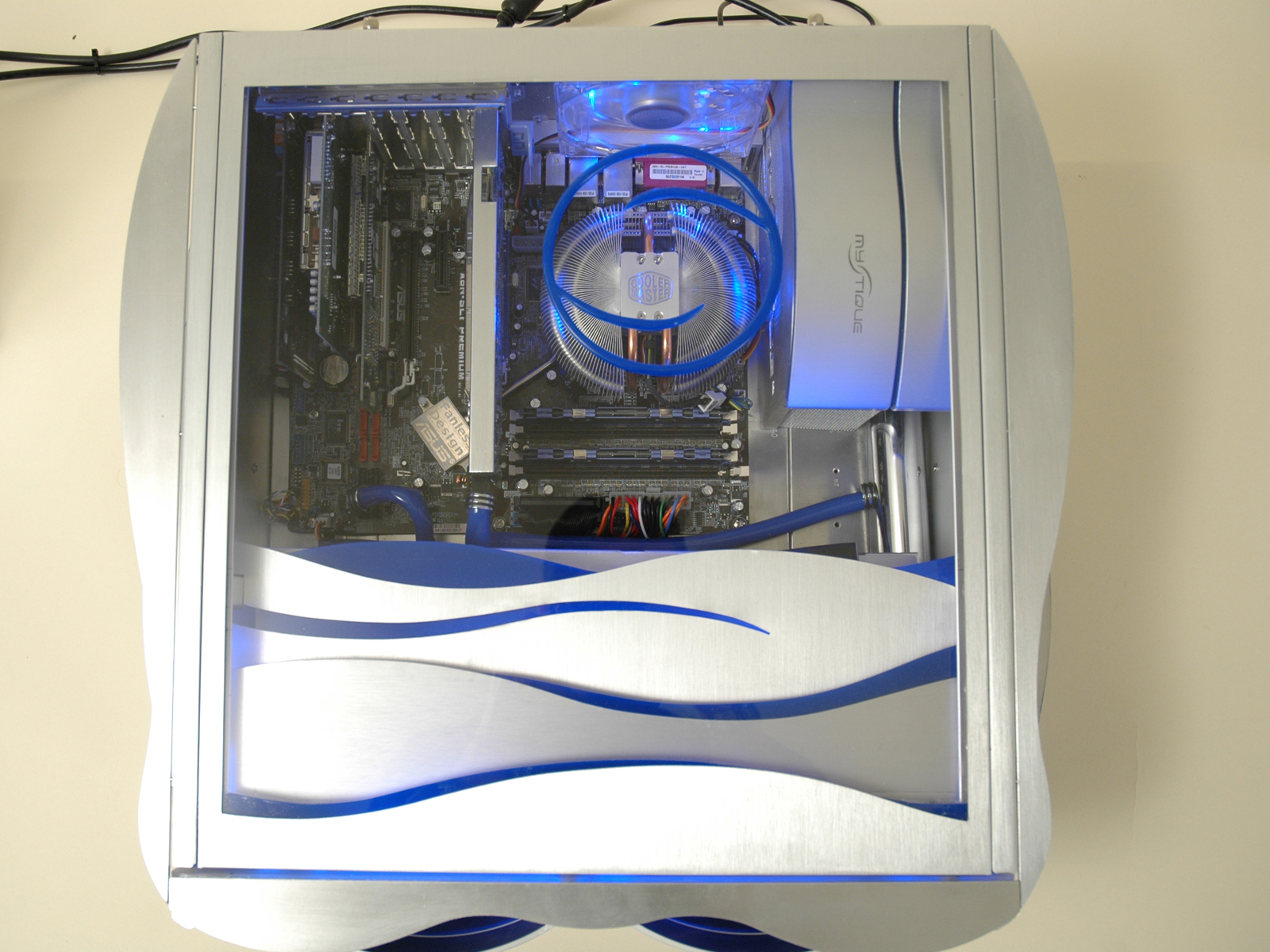
The top window has a wavy design element at the front over the DVD drives,

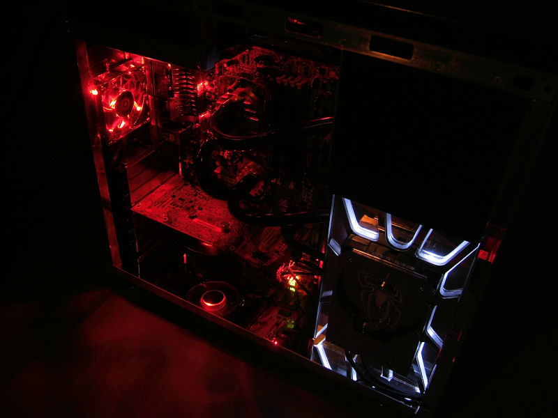
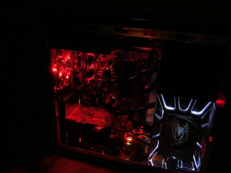
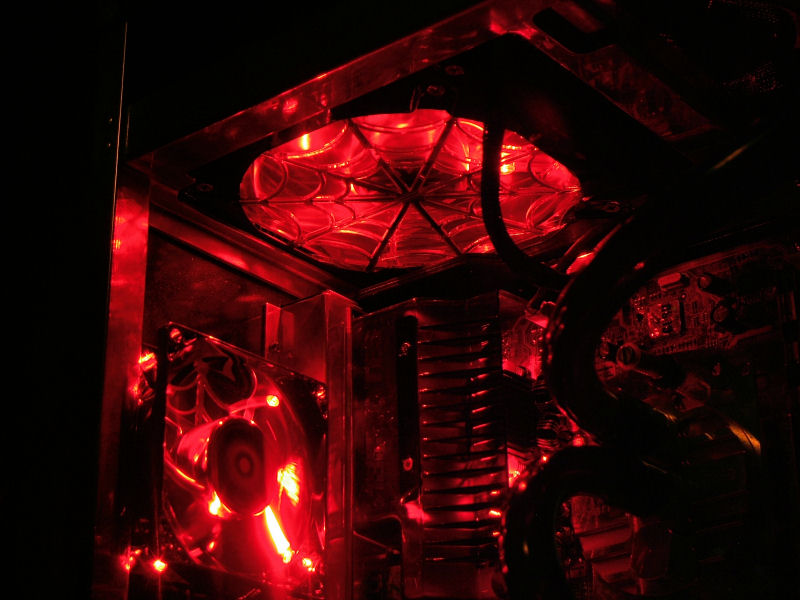
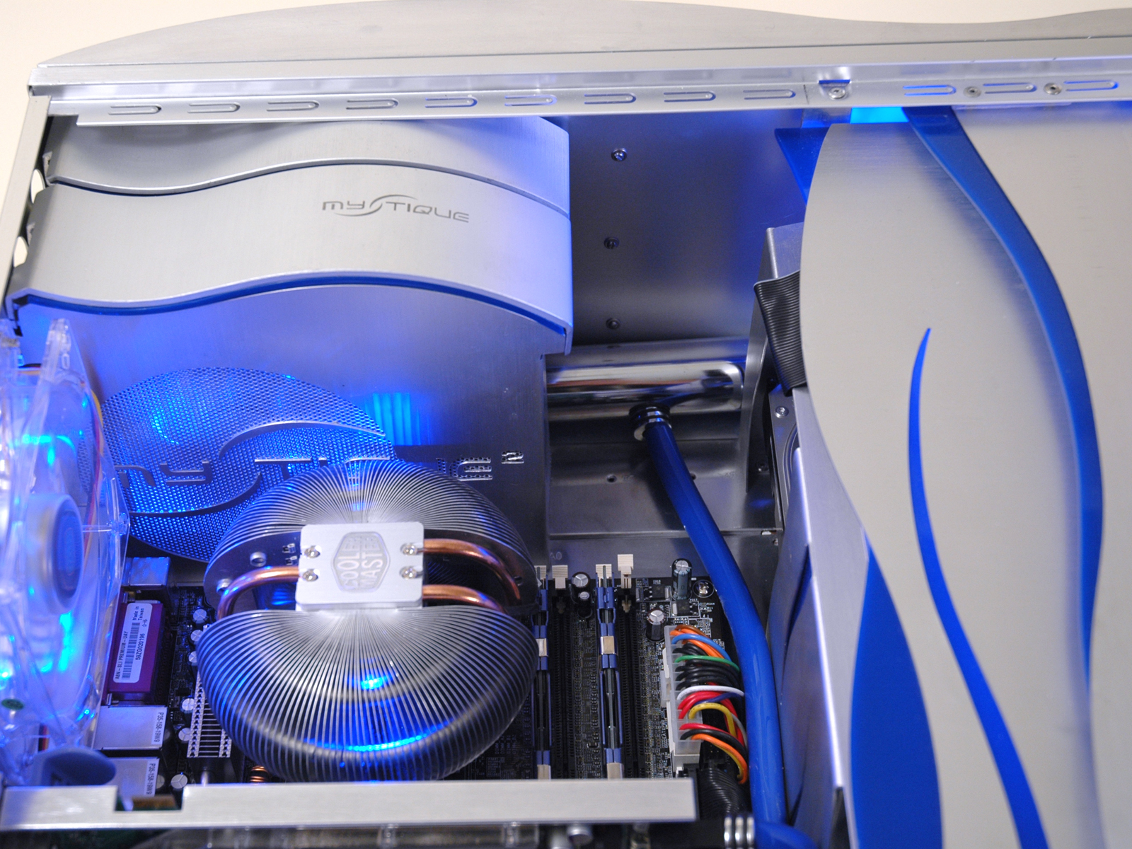
and a blue plexi ring centered over the Mars cpu cooler.


Since the new sides used to be the old tops of the cases, they still have the IO port holes, except now they are blue-lit logo badges.

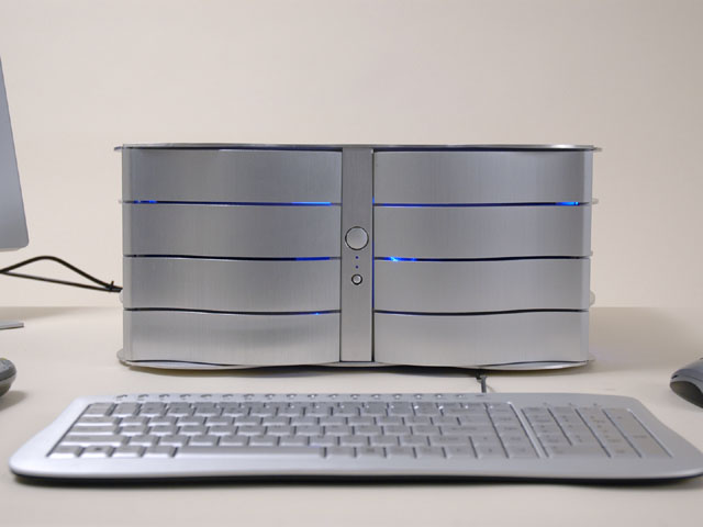
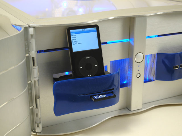
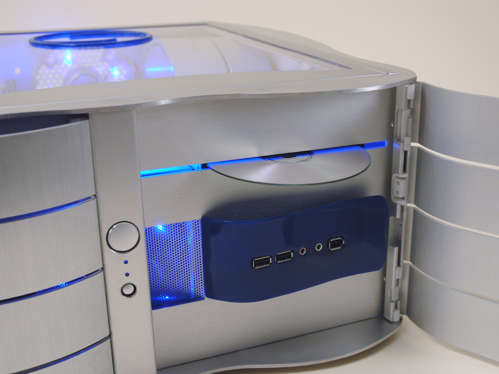
The new IO panel resides inside the front doors in a decorative blue wave. Opposite the IO panel is a 10-in-1 card reader that pulls out to reveal an iPod docking station.


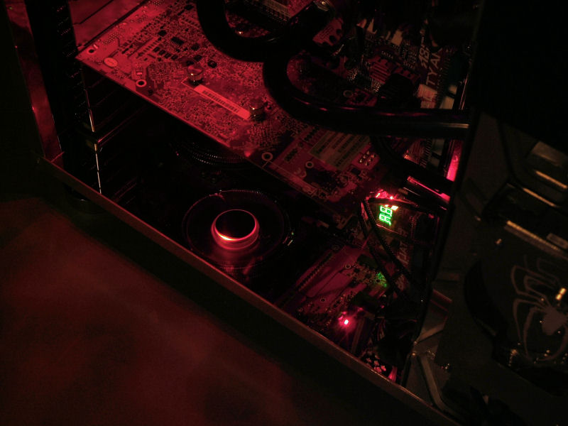
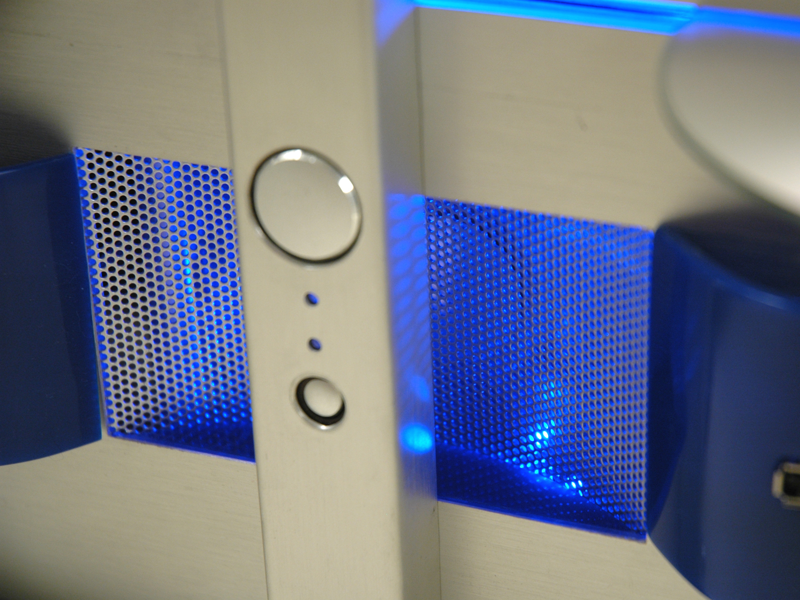
Centered in between the two blue waves is the air intake for the front fan, complete with concaved mesh behind the power/reset button post.

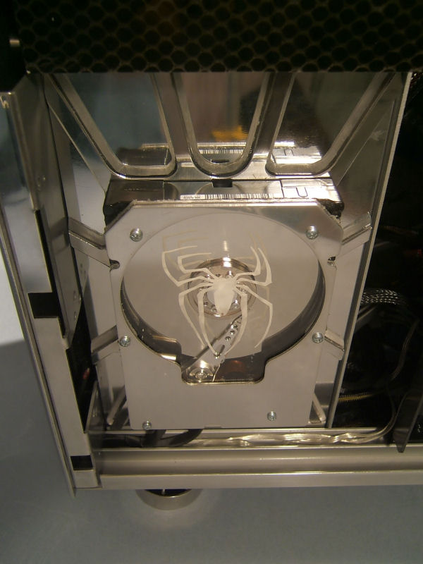
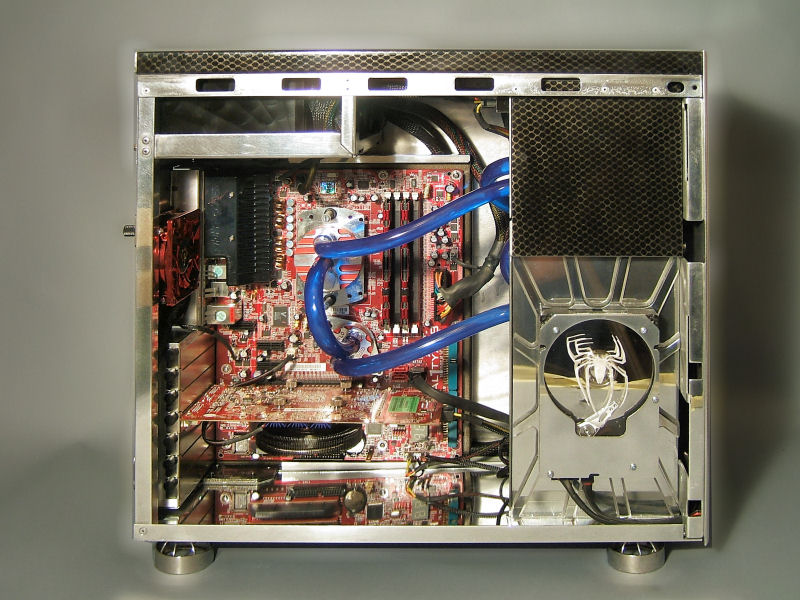
Inside the case, I built an entirely new drive cage, having gutted its original contents. I incorporated the original tool-less cages back into the new design, adding an intake fan in between them. The DVD drives are mounted on top, and a stylish rear cover was devised to direct cool air through both sides before entering the main part of the case.

The drives are perfectly aligned so that one could insert a disc without having to open the doors.


The power supply was concealed utilizing more original front bezel parts and brushed aluminum side paneling.

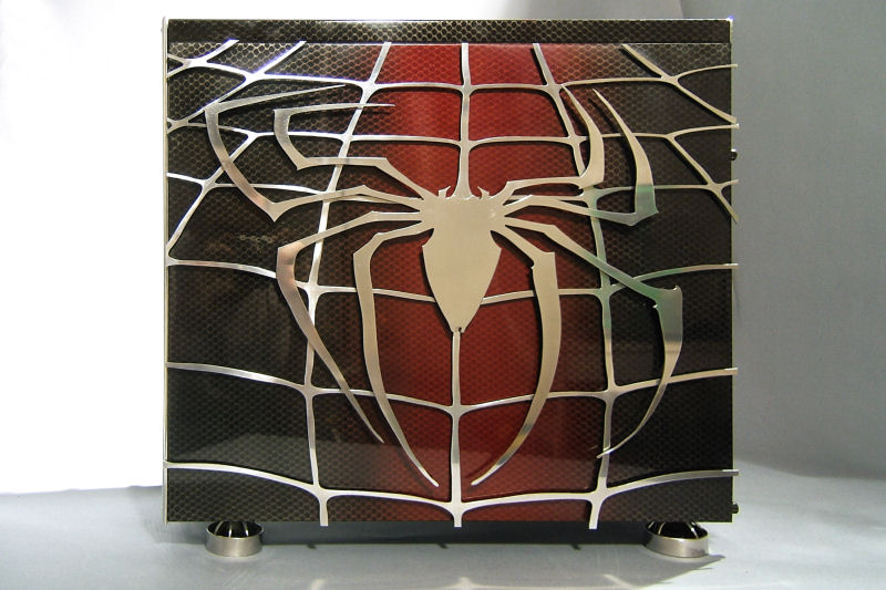
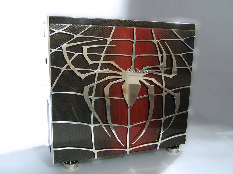
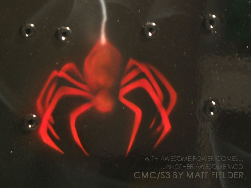
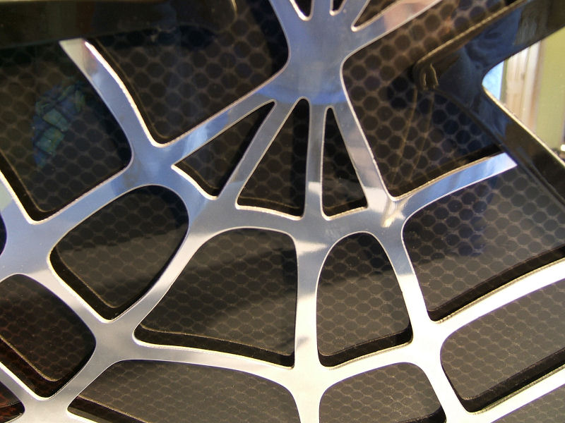
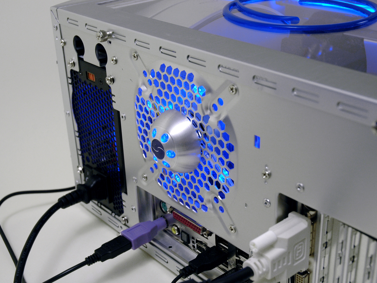
I incorporated the logo into the fan grill, complete with individually cut lettering (cut by hand from the existing aluminum panel) and mesh behind the whole thing. Blue plexi separates the side piece from the top wavy piece.

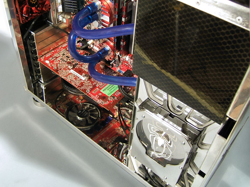
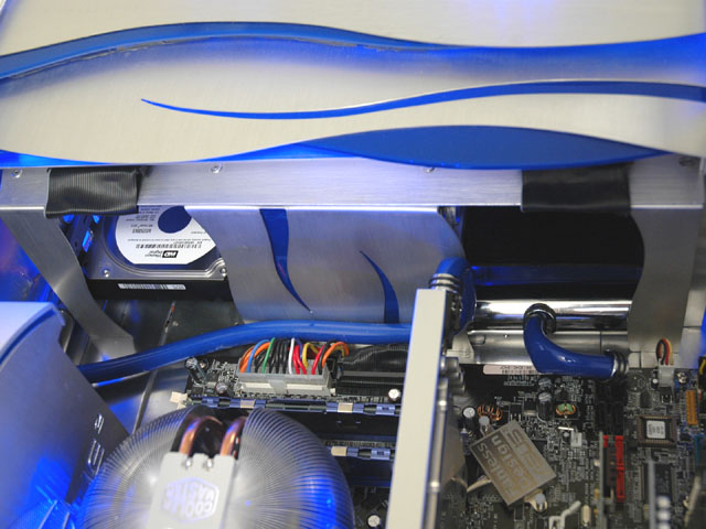
Wire management was achieved by running the power cables first through a piece of 2 ¼” chrome pipe. They then branch off to their destinations underneath the motherboard tray, emerging only where they plug in. The video card power cable and SATA cable take exception to the rule, and are sleeved in blue silicon hosing with chrome end caps.


For added lighting in the back, I incorporated a brushed aluminum led dome into the center of the exhaust fan's grill. It is battery operated, and serves to light the cable hookups even when the PC is turned off.

Every effort was taken to recycle items from the original cases. The only non-indigenous parts are the blue plexi pieces, a few support pieces and the exterior fins (made from aluminum stock purchased from the hardware store).
The keyboard and mouse were chosen to match the case perfectly. It being an HTPC, it will connect to my Samsung 50" DLP television. A WinPVR150 tv tuner card, Cats Eye HDTV tuner card, a TERK indoor HD antenna and Windows XP Media Edition with a Logitech Harmony remote round out the system.
Not shown are the original stylish case feet that were relocated to what used to be the right side panel (now the bottom of the case).
© Brian Carter 2007
this isa copy paste from his site.This is named as mystique as it features a mystique 631 case.A very valuable casing.
MYSTIQUE²
STORY:
I came up with the idea to create one HTPC desktop-style case using two Mystique 631 aluminum tower chassis. The main idea was to keep evident the Mystique heritage and styling throughout the case, inside and out. The wavy theme was carried out in tandem with logo elements to create a consistent and elegant look, while keeping its ultimate use in mind. This being a home theater PC, it will be located in my living room, and must function as a HDTV tuner/personal video recorder. Care was taken when selecting components that were best suited for such a task (i.e. Mars cpu cooler running in silent mode).
System Specs:
Asus A8N SLI Premium Motherboard
AMD FX-55 cpu with CM Mars cooler
Centon PC-3200 RAM (1Gb)
Geforce XFX 7800GT Video Card
Sound Blaster Audigy Sound Card
Western Digital SATA 200Gb Hard Drive
Cooler Master 600W eXtreme Power PSU
Pioneer Slim-line Slot Loading DVD drive (x2)
WinPVR Tv-tuner PCI card
Cats Eye HDTV tuner PCI card
Zippy Aluminum Keyboard
Logitech Cordless Mouse
iDuo 10-in-1 Card Reader/iPod Dock
I wanted to design the case in such a way as to make people immediately think "Mystique" when they first see it.
The Mystique's signature front wavy doors were retained, and aluminum fins were added on both sides and aligned with the doors' slots, continuing the wavy theme around the case.
The top window has a wavy design element at the front over the DVD drives,
and a blue plexi ring centered over the Mars cpu cooler.
Since the new sides used to be the old tops of the cases, they still have the IO port holes, except now they are blue-lit logo badges.
The new IO panel resides inside the front doors in a decorative blue wave. Opposite the IO panel is a 10-in-1 card reader that pulls out to reveal an iPod docking station.
Centered in between the two blue waves is the air intake for the front fan, complete with concaved mesh behind the power/reset button post.
Inside the case, I built an entirely new drive cage, having gutted its original contents. I incorporated the original tool-less cages back into the new design, adding an intake fan in between them. The DVD drives are mounted on top, and a stylish rear cover was devised to direct cool air through both sides before entering the main part of the case.
The drives are perfectly aligned so that one could insert a disc without having to open the doors.
The power supply was concealed utilizing more original front bezel parts and brushed aluminum side paneling.
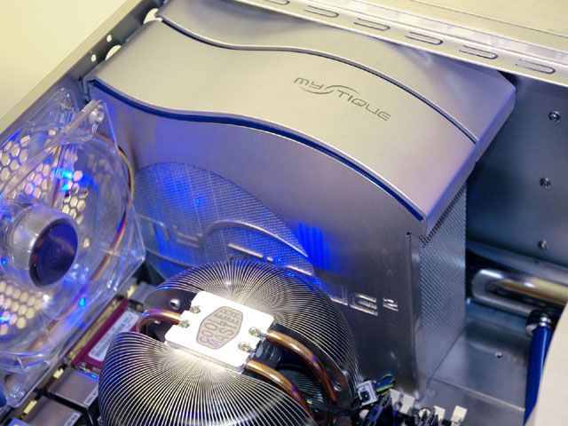
I incorporated the logo into the fan grill, complete with individually cut lettering (cut by hand from the existing aluminum panel) and mesh behind the whole thing. Blue plexi separates the side piece from the top wavy piece.

Wire management was achieved by running the power cables first through a piece of 2 ¼” chrome pipe. They then branch off to their destinations underneath the motherboard tray, emerging only where they plug in. The video card power cable and SATA cable take exception to the rule, and are sleeved in blue silicon hosing with chrome end caps.
For added lighting in the back, I incorporated a brushed aluminum led dome into the center of the exhaust fan's grill. It is battery operated, and serves to light the cable hookups even when the PC is turned off.
Every effort was taken to recycle items from the original cases. The only non-indigenous parts are the blue plexi pieces, a few support pieces and the exterior fins (made from aluminum stock purchased from the hardware store).
The keyboard and mouse were chosen to match the case perfectly. It being an HTPC, it will connect to my Samsung 50" DLP television. A WinPVR150 tv tuner card, Cats Eye HDTV tuner card, a TERK indoor HD antenna and Windows XP Media Edition with a Logitech Harmony remote round out the system.
Not shown are the original stylish case feet that were relocated to what used to be the right side panel (now the bottom of the case).
© Brian Carter 2007
 That other one was an utter mess